
Communication system and communication equipment

A technology of communication equipment and communication system, which is applied in the field of communication systems, can solve problems such as incompatible radio communication and failure to realize radio communication, and achieve the effect of reducing wiring costs

Inactive Publication Date: 2007-04-25
YOKOGAWA ELECTRIC CORP
View PDF1 Cites 6 Cited by
  • Summary
  • Abstract
  • Description
  • Claims
  • Application Information

AI Technical Summary

Problems solved by technology

However, radio communication has not been realized in the related art described above due to the following reasons:
[0016] (a) many field devices are not compatible with radio communications; and

Method used


Image

  • Communication system and communication equipment
  • Communication system and communication equipment
  • Communication system and communication equipment

Examples


Embodiment Construction

[0048] Hereinafter, embodiments of the present invention will be described in detail with reference to the accompanying drawings.

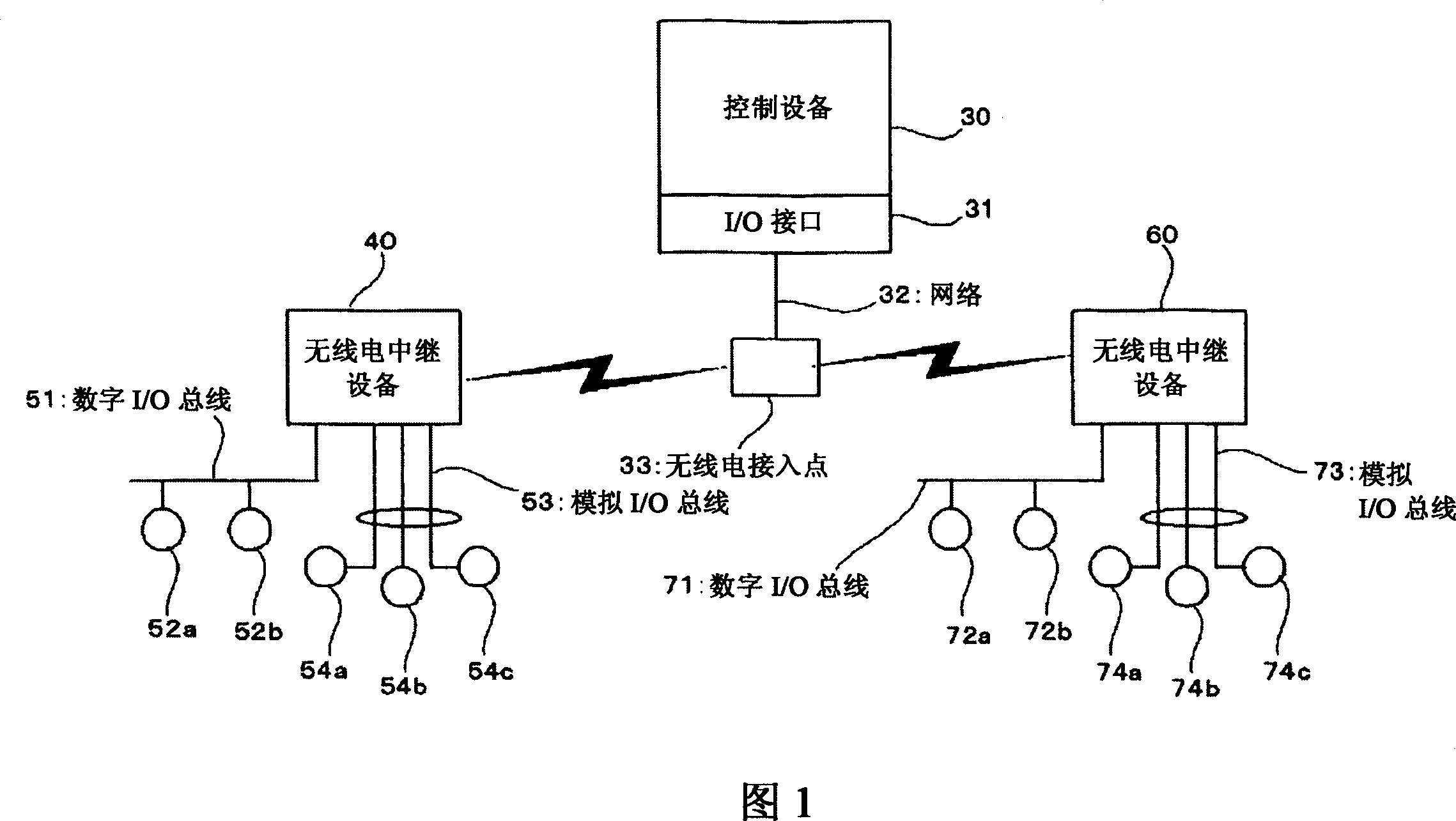
[0049] FIG. 1 is a diagram showing the structure of one embodiment of the communication system of the present invention.

[0050] In FIG. 1 , the control device 30 corresponds to the control device 2 in FIG. 4 . The control device 30 is equipped with an I / O interface 31 . The radio access point 33 is connected to the I / O interface 31 via a general-purpose network 32 such as Ethernet (registered trademark). The radio communication system utilized by the I / O interface 31 and the radio access point 33 is a system generally used in an office environment, such as IEEE 802.11a / b / g.

[0051] The I / O interface 31 inputs and outputs signals by using a standardized communication protocol. The radio access point 33 performs radio communication via a standardized communication protocol.

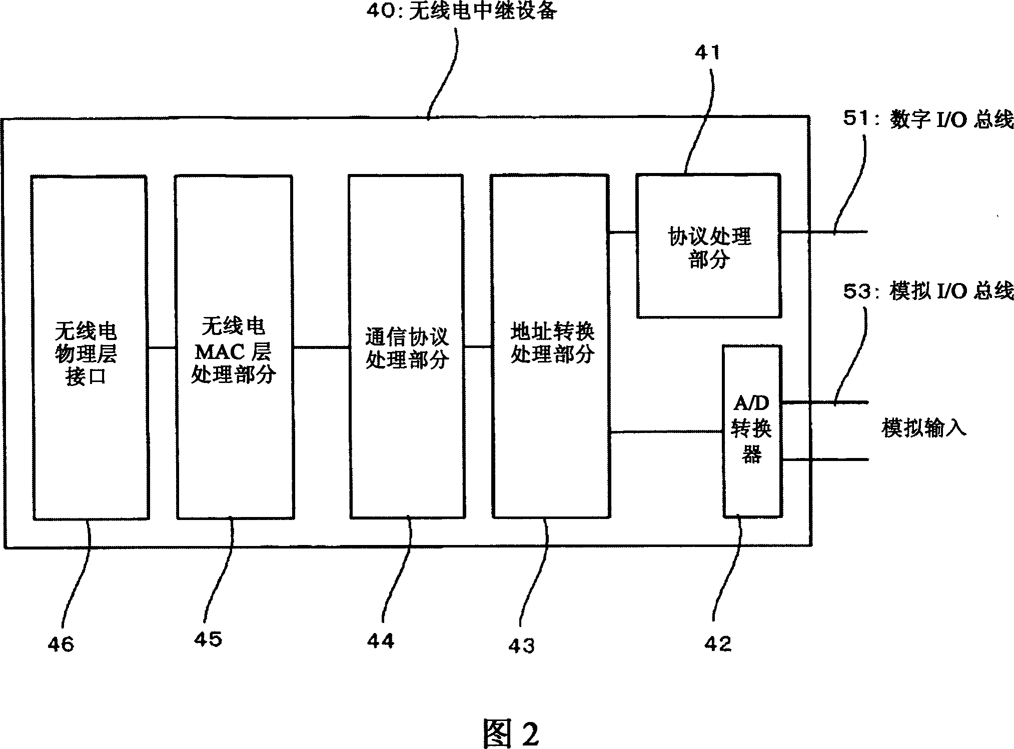
[0052] The digital I / O bus 51 is connected to a radio repeater 40 ....


PUM


Abstract

Communication equipment provided in a communication system is connected with field equipment. The communication equipment performs wireless communication with a controller which controls a plant wherein the field equipment is arranged, by following a standardized communication protocol, and relays communication between the field equipment and the controller.

Description

technical field [0001] The present invention relates to a communication device, and also to a communication system having the communication device, wherein a field device is connected to the communication device, and the communication device relays the field device and the Communications between the control devices of the plant for control. Background technique [0002] Field devices are installed in plants in petrochemical, steel, paper, food, pharmaceutical, and power industries, among others. Such plants are controlled by distributed control systems. [0003] FIG. 4 is an exemplary configuration diagram showing a commonly used distributed control system. [0004] In FIG. 4 , an operation monitoring device 1 and a control device 2 are connected to a control bus 3 . The control device 2 controls the factory 4 under the monitoring of the operation monitoring device 1 . The operation monitoring apparatus 1 performs operational operation and monitoring of the plant. The o...

Claims


Application Information

Patent Timeline
Patent Type & Authority Applications(China)
IPC IPC(8): G05B23/02H04B7/26H04L12/28G05B15/02H04B7/155
CPCG05B15/02G05B2219/33192
Inventor 小川永志树富田俊郎星哲夫出町公二高桥博文齐藤洋二野口昌德
Owner YOKOGAWA ELECTRIC CORP
Learn More