Working vehicle

A vehicle and machine body technology, applied in the field of driving vehicles for work, can solve problems such as engine corrosion and shortened life, and achieve the effects of preventing fertilizer clogging and excellent driving performance

Inactive Publication Date: 2007-05-02
ISEKI & CO LTD
View PDF1 Cites 9 Cited by
  • Summary
  • Abstract
  • Description
  • Claims
  • Application Information

AI Technical Summary

Problems solved by technology

[0003] However, there is a problem that the fertilizer splashed from the fertilization device near the engine installed in the central part of the aircraft falls on the engine, corrodes the engine, and shortens its life.

Method used


Image

  • Working vehicle
  • Working vehicle
  • Working vehicle

Examples


Embodiment Construction

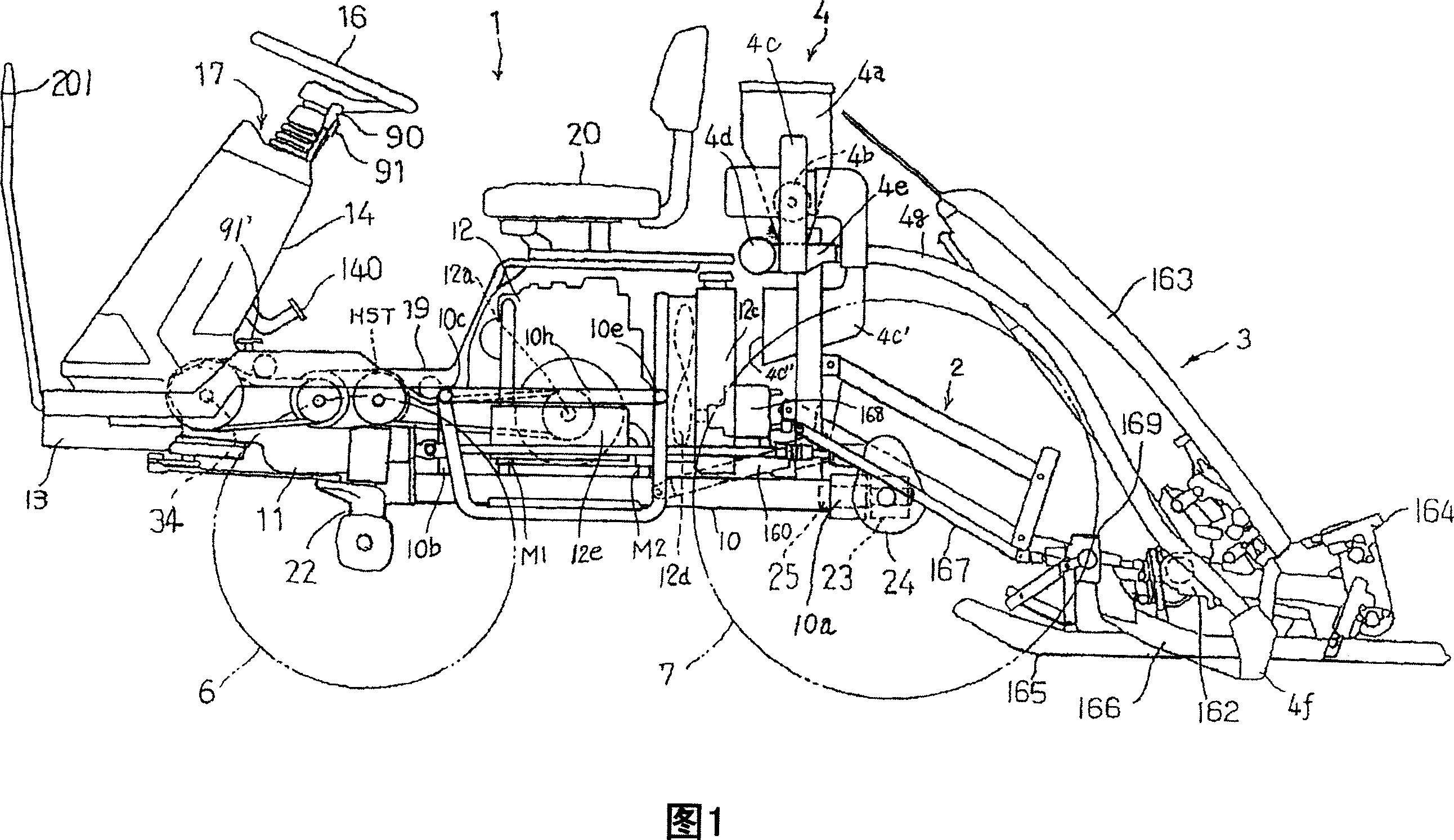
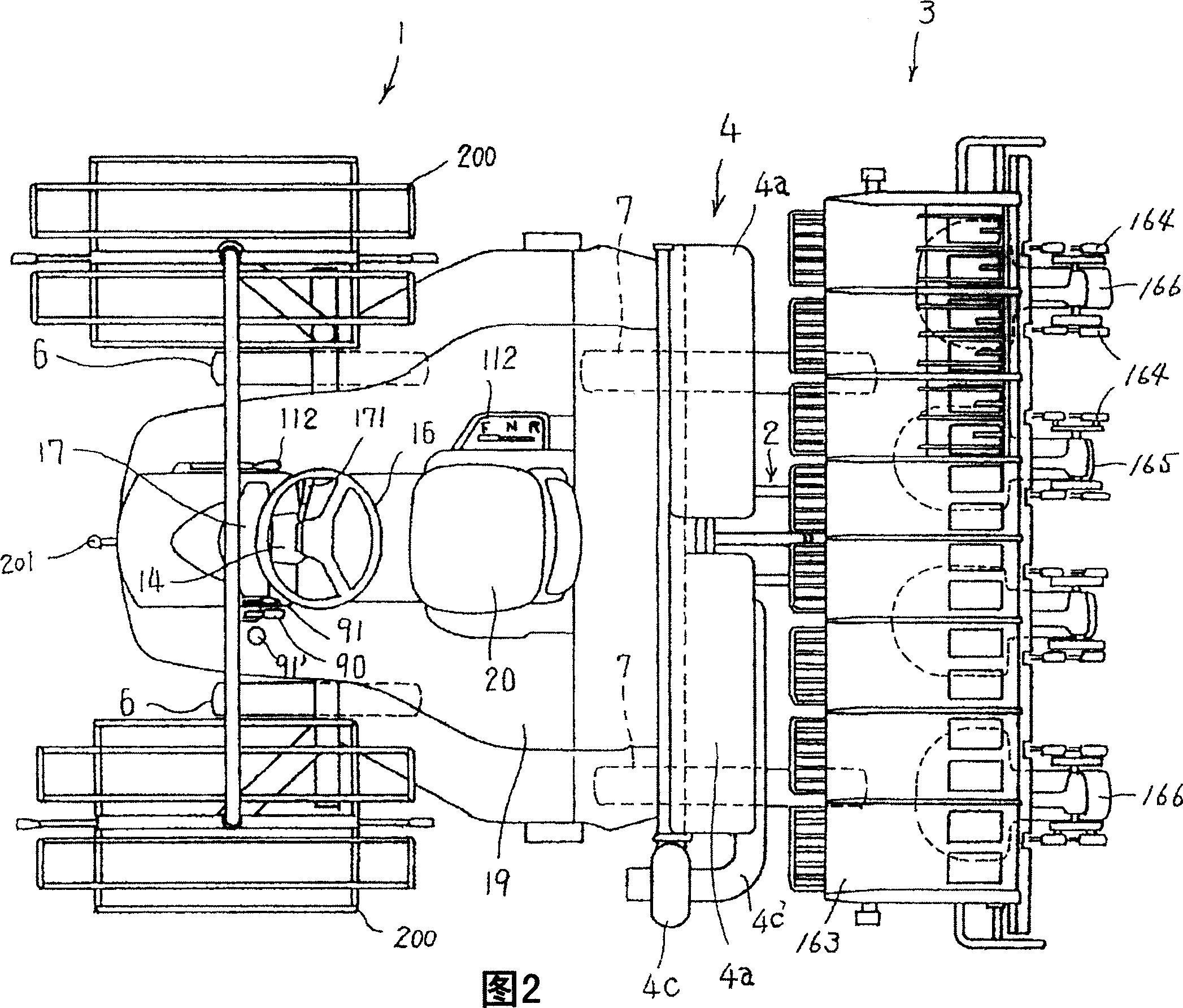
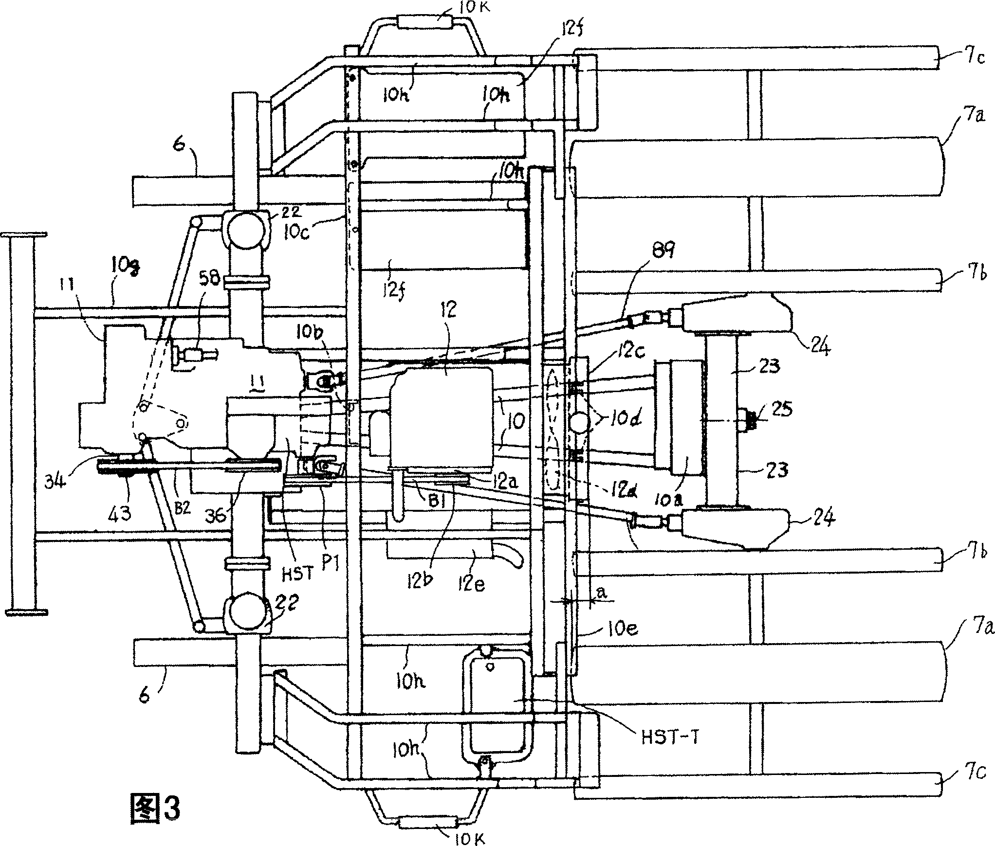
[0018] The eight planting manned rice transplanters of an embodiment of the present invention are described in detail according to the accompanying drawings. On the traveling vehicle 1, a rice transplanting device 3, which is a kind of working device, is installed with a lifting link device 2, and a fertilization device 4 is installed at the same time, so as to constitute a manned type fertilization and rice transplanter as a whole. The traveling vehicle 1 is a four-wheel drive vehicle having a pair of left and right front wheels 6, 6 and rear wheels 7, 7 as drive wheels. In addition, the left and right rear wheels 7, 7 are respectively composed of a main wheel 7a, a slightly smaller-diameter inner auxiliary wheel 7b, and an outer field wheel 7c in order to improve traction.

[0019] A transmission case 11 is bolted to front portions of the left and right main frames 10 , 10 , and a steering column 14 is protruded upward from the front portion of the transmission case 11 .

...


PUM


Abstract

The overpast working vehicle has the problem of that the fertilizer from the fertilizer drilling unit, adjacent to an engine arranged on the center of the body, falls down to the engine and corrupts the engine, thus the life of the engine is reduced. In order to overcome the problem, the present invention provides a working vehicle wherein an engine(12)is arranged on the center of the body and a fertilizer tank(4a)of the fertilizer drilling unit(4)is arranged on the back part of the body, which is characterized in that a structure of arranging a radiator(12c)in the back part of the engine(12)and discharging the waste heat of the engine to the back of the body by heat emission fan(12d)is provided, and an outputting device(4b)for outputting the fertilizer inside of the fertilizer tank(4a)is arranged on the fertilizer drilling unit(4), and a blower(4c)for sucking air from the back side of the radiator(12c)to generate pressure wind for conveying the fertilizer outputted from the outputting device(4b)is provided.

Description

technical field [0001] The present invention relates to a working vehicle on which a fertilization device is mounted. Background technique [0002] Conventionally, there is a traveling vehicle for work in which an engine is mounted in the center of the body and a fertilizing device is installed in the rear of the body. (Refer to Patent Document 1-JP-A-2003-154858) [0003] However, there is a problem that the fertilizer splashed from the fertilization device near the engine mounted in the central part of the body falls on the engine, corrodes the engine, and shortens its life. Contents of the invention [0004] In order to solve the above-mentioned problems, the invention described in scheme 1 is a kind of engine 12 is mounted on the central part of the body, and the fertilizer tank 4a of the fertilization device 4 is set at the rear of the body. The radiator 12c is configured in the rear to discharge the exhaust hot air of the engine to the rear of the body through the ...

Claims


Application Information

Patent Timeline
Patent Type & Authority Applications(China)
IPC IPC(8): A01C15/04A01C19/00F01N5/04
CPCY02T10/16Y02T10/12B60K11/04B60K17/00F01P2070/52
Inventor 清家理伯福村善宏冲本章
Owner ISEKI & CO LTD
Why Eureka
Try Eureka