Method of reproducing tomography image of object

A tomography and object technology, applied in image enhancement, image generation, image data processing, etc., can solve the problems of slow clinical application, and achieve the effect of reducing times and calculation time

Inactive Publication Date: 2007-05-02
SIEMENS AG
View PDF0 Cites 12 Cited by
  • Summary
  • Abstract
  • Description
  • Claims
  • Application Information

AI Technical Summary

Problems solved by technology

[0011] Paper by Mueller K.: "Fast and accurate three-dimensional reconstruction from Cone-Beam projection data using Algebraic Methods", Ohio State Univ., 1998 Although an improved iterative reconstruction method is disclosed, it is based on a solution using a graphics card , but this method still requires twice the number of iterations multiplied by the duration of the filtered backprojection, so it is still too slow for clinical use in practice

Method used


Image

  • Method of reproducing tomography image of object
  • Method of reproducing tomography image of object
  • Method of reproducing tomography image of object

Examples


Embodiment Construction

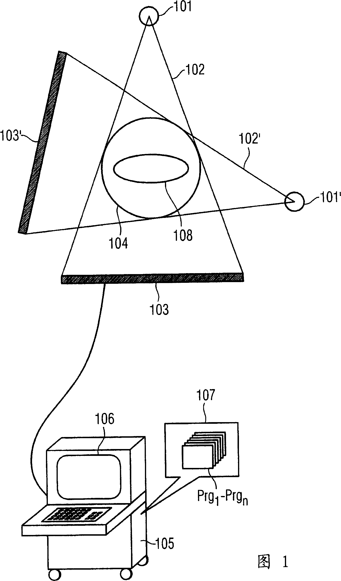
[0038] FIG. 1 shows a known typical CT setup with an X-ray source 101 at a first location emitting an X-ray beam 102 for a first projection, which is passed through an X-ray beam at a re-site 104 to be examined. The object, in this case the patient 108 , is then detected by the detector 103 at this first position. The data from the detectors are transferred to the analysis computer 105 for reproduction and then displayed on the display unit 106 . The x-ray source 101 moves ideally on a circular path, wherein a large number of projections are recorded from different angles. Also shown in FIG. 1 is an X-ray source 101' at another angular position, wherein an X-ray beam 102' is emitted for another projection, which is then detected by a detector 103 at another position 'detected.

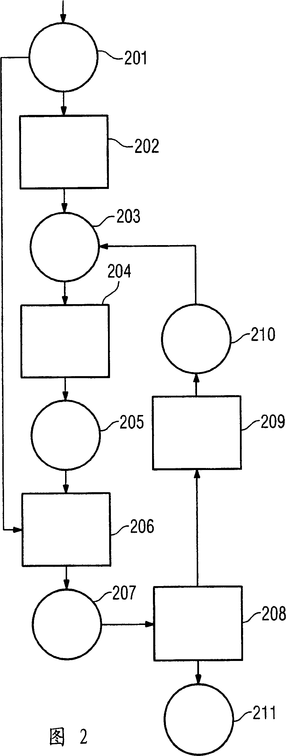
[0039] FIG. 2 depicts the implementation of a conventional iterative reconstruction: in step 202 the measured projection (forward projection) 201 is back-projected onto the object to be reconstructed...


PUM


Abstract

A method is disclosed for the iterative analytical reconstruction of a tomographic representation of an object from projection data of a moving radiation source through this object onto a detector. In an embodiment of the method, corrections are undertaken iteratively with the aid of back projections of the object to be represented from calculated projection data, wherein the corrections are performed on the projections.

Description

technical field [0001] The invention relates to a method for iteratively analyzing a tomographic image of a reconstructed (ART) object from projection data of a moving radioactive source passing through the object and falling on a detector, in which reconstruction method iteratively starts from a calculated Correction is carried out by using the back projection of the object to be displayed in the projected data. Background technique [0002] Computed tomography (CT) provides medical and laboratory technology with a diagnostic and measurement method by which the internal structures of patients or subjects can be examined without intervening in the patient or damaging the subject in the process. In this case, several projections are recorded from different angles of the object to be examined, from which projections a three-dimensional description of the object can be calculated. [0003] It is generally known to solve this problem by means of the so-called Filtered Back Proj...

Claims


Application Information

Patent Timeline
Patent Type & Authority Applications(China)
IPC IPC(8): G06T5/00A61B6/03
CPCG06T11/006G01N2223/419G06T2211/424G01N29/0672G01N23/046
Inventor 霍尔格·孔泽
Owner SIEMENS AG
Why Eureka
Try Eureka