
Vapor/liquid separation apparatus for use in cracking hydrocarbon feedstock containing resid

A hydrocarbon raw material and equipment technology, applied in the field of vapor/liquid separation equipment, can solve the problems of removal and low efficiency

Active Publication Date: 2007-05-02
EXXONMOBIL CHEM PAT INC
View PDF7 Cites 3 Cited by
  • Summary
  • Abstract
  • Description
  • Claims
  • Application Information

AI Technical Summary

Problems solved by technology

The two-phase mist stream presents operational problems in the flash drum because at these high gas flow rates, the small liquid droplets containing non-volatile hydrocarbons do not coalesce and therefore cannot be efficiently removed from the flash drum as a liquid phase. remove
It was found that at a gas flow rate of 30 m / sec (100 ft / sec), the flash drum was only capable of removing heavy non-volatile hydrocarbons at a low efficiency of, for example, about 73%

Method used


Image

  • Vapor/liquid separation apparatus for use in cracking hydrocarbon feedstock containing resid
  • Vapor/liquid separation apparatus for use in cracking hydrocarbon feedstock containing resid
  • Vapor/liquid separation apparatus for use in cracking hydrocarbon feedstock containing resid

Examples


Embodiment Construction

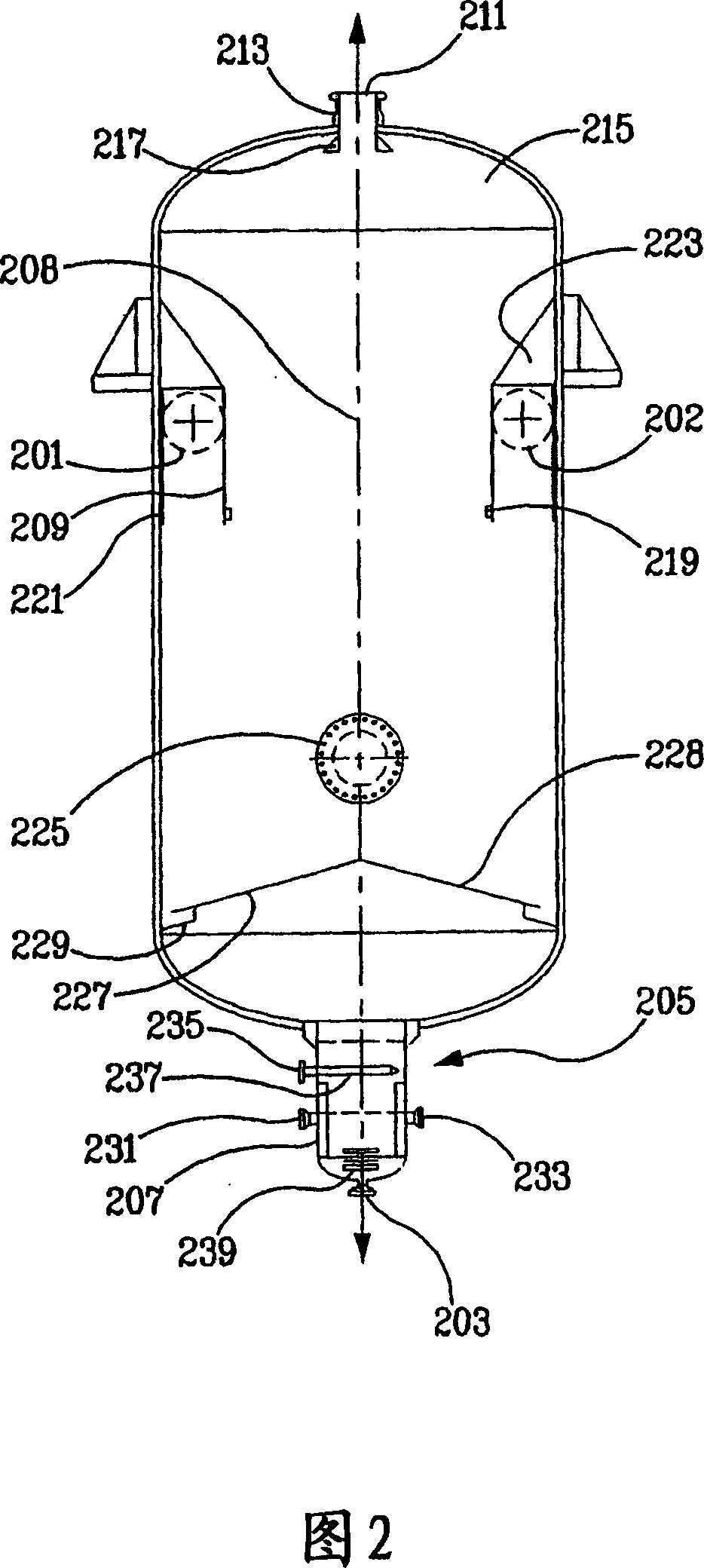
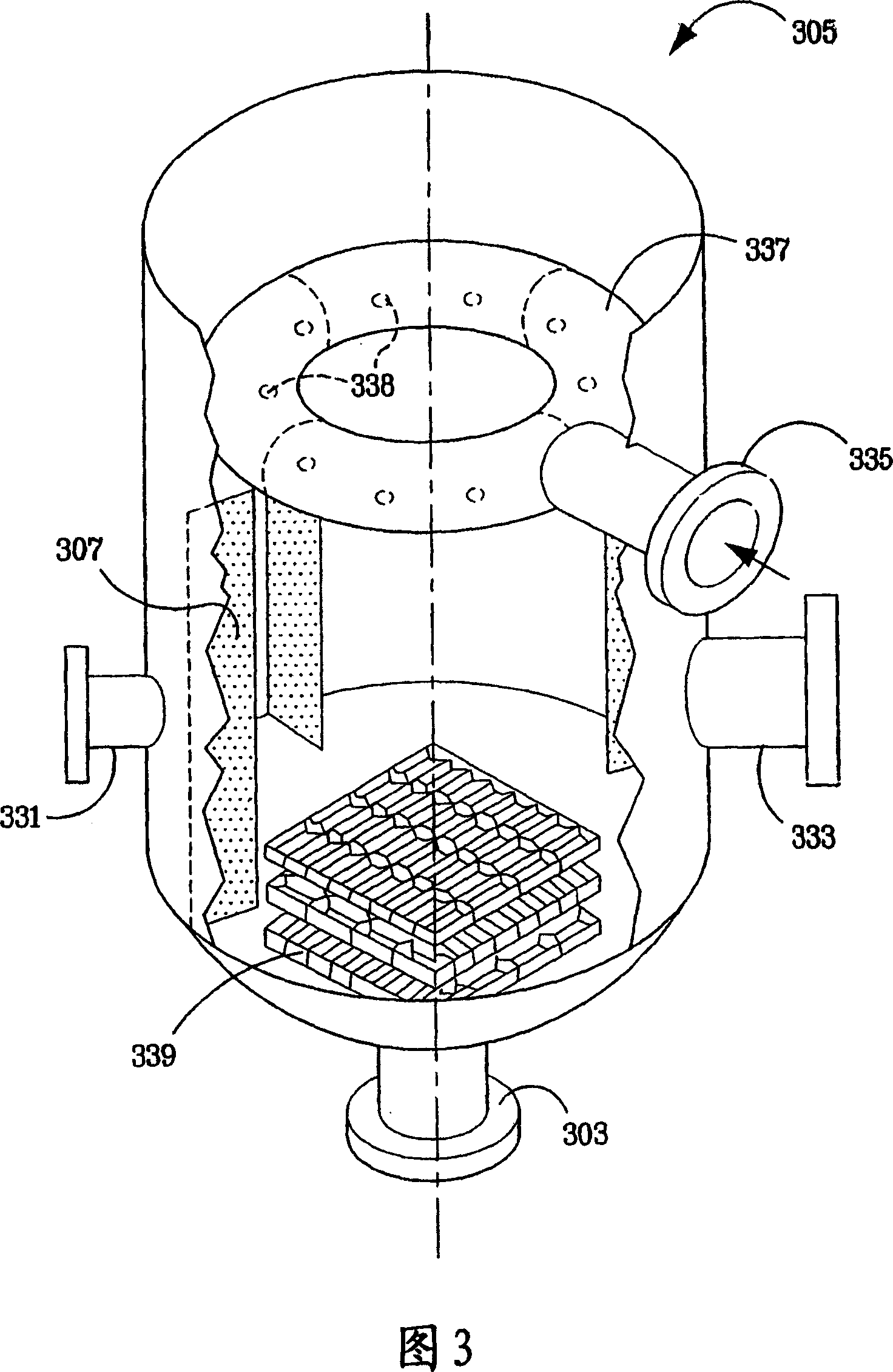
[0024] This invention relates to efficient vapor / liquid separation equipment for processing fluids of vapor / liquid mixtures of hydrocarbons and steam. The apparatus consists of a substantially cylindrical vertical drum or vessel having an upper cover section, a middle section comprising circular walls and a lower cover section, a tangential inlet for the introduction of a hydrocarbon / vapour mixture, an overhead vapor outlet, and a liquid bottom exit. The container also includes an annular structure located in the middle section, the annular structure comprising: (i) an annular top section extending from the circular wall and (ii) a coaxial inner vertical side wall into which the top section extends. The annular structure intercepts the upward passage of the vapor / liquid mixture along the circular wall beyond the top section, and the annular structure surrounds an open core having sufficient cross-sectional area to allow the vapor velocity to be low enough Avoid significant en...


PUM


Abstract

A highly efficient vapor / liquid separation apparatus for treating a flow of vapor / liquid mixtures of hydrocarbons and steam comprises a substantially cylindrical vertical drum having an upper cap section, a middle section comprising a circular wall, a lower cap section, a tangential inlet to introduce hydrocarbon / steam mixtures, an overhead vapor outlet, and a bottom outlet for liquid. The vessel also comprises an annular structure located in the middle section, comprising i) an annular ceiling section extending from the circular wall and ii) a concentric internal vertical side wall to which the ceiling section extends. The annular structure blocks upward passage of vapor / liquid mixtures along the circular wall beyond the ceiling section, and surrounds an open core having sufficient cross-sectional area to permit vapor velocity low enough to avoid significant entrainment of liquid.

Description

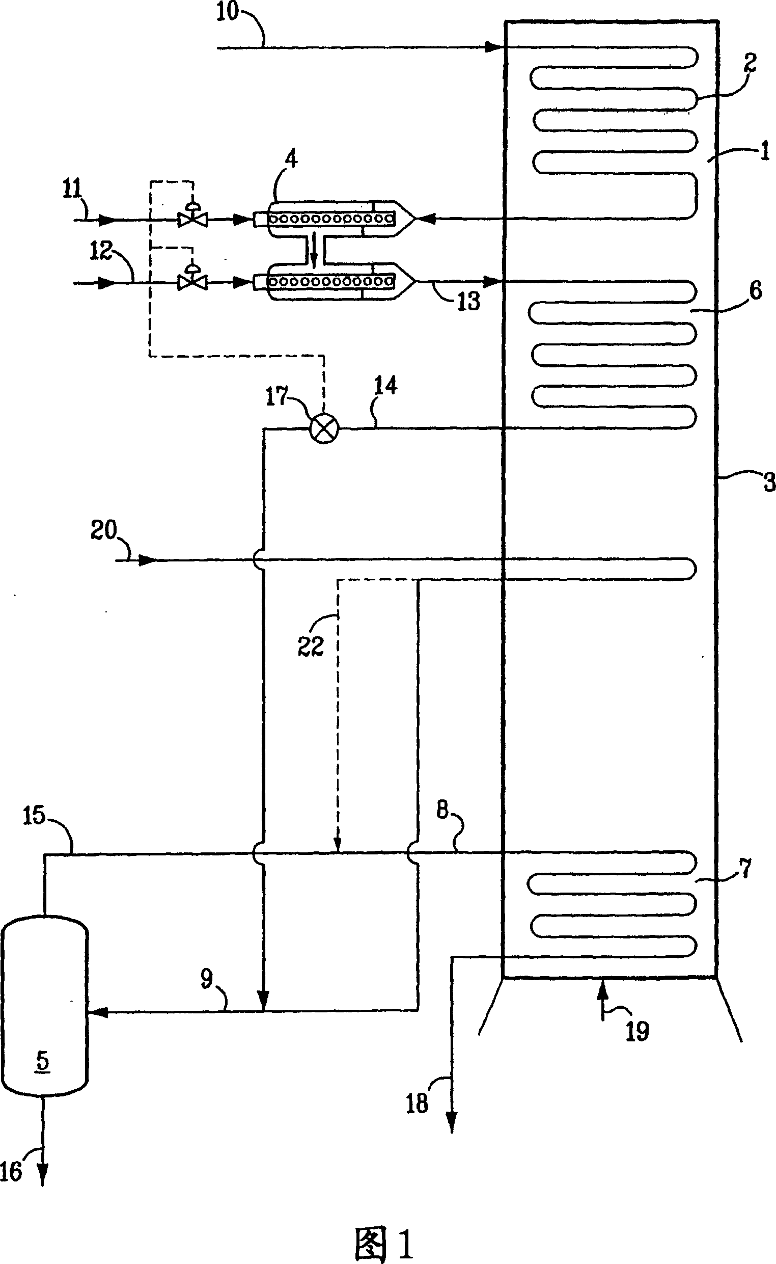
field of invention [0001] This invention relates to vapor / liquid separation apparatus exhibiting high efficiency in the removal of non-volatile hydrocarbons from hydrocarbon feedstocks. Background of the invention [0002] Steam cracking (also known as pyrolysis) has long been used to crack various hydrocarbon feedstocks into olefins, preferably light olefins such as ethylene, propylene and butenes. Conventional steam cracking uses a pyrolysis furnace with two main sections: a convection section and a radiant section. The hydrocarbon feed usually enters the convection section of the furnace as a liquid (except for light feeds entering as vapour), where the hydrocarbon feed is heated and gasified, usually by indirect contact with hot flue gas from the radiant section and by direct contact with steam . The gasified feedstock and steam mixture is then introduced into the radiant section where cracking occurs. The resulting product, including olefins, exits the pyrolysis furn...

Claims


Application Information

Patent Timeline
IPC IPC(8): C10G9/20C10G9/00B01D19/00
CPCC10G2300/104C10G2300/1055C10G2300/1022C10G9/20C10G2300/1044C10G2300/807C10G9/00C10G2300/1077C10G2400/20B01D19/0036C10G2300/1059C10G2300/1051C10G2300/1074C10G2300/107C10G2300/1033Y02P30/40
Inventor R·C·斯特A·R·迪尼克兰托尼奥G·斯蒂芬斯J·M·弗莱伊
Owner EXXONMOBIL CHEM PAT INC
Learn More