Apparatus for spinning and winding several synthetic threads

Technology of a spinning device, thread, applied in the field of spinning and winding devices

Inactive Publication Date: 2010-07-21
SAURER GMBH & CO KG
View PDF7 Cites 0 Cited by
  • Summary
  • Abstract
  • Description
  • Claims
  • Application Information

AI Technical Summary

Problems solved by technology

Although the distribution width of the winding unit can be reduced in this way, it has the disadvantage that a thread guide occurs between the upper winding unit and the lower winding unit
Especially when it is possible to wind synthetic yarns at high speeds above 6000m / min, this difference in guide length produces different winding tensions due to air resistance in the yarn guidance, thus resulting in different quality bobbins and even yarns

Method used


Image

  • Apparatus for spinning and winding several synthetic threads
  • Apparatus for spinning and winding several synthetic threads
  • Apparatus for spinning and winding several synthetic threads

Examples


Embodiment Construction

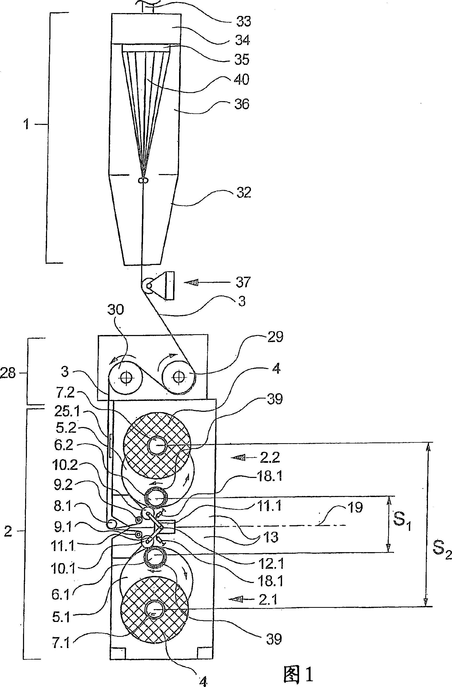
[0035] exist figure 1The middle outline shows a view of a first exemplary embodiment of the device according to the invention. The device has a spinning device 1 , a drawing device 28 arranged below the spinning device 1 and a winding unit group 2 arranged below the drawing device 28 with winding units 2 . 1 and 2 . 2 .

[0036] The spinning device 1 is connected via a melt inlet 33 to a melt source (not shown here), for example an extruder. The melt inlet 33 leads to a spinning beam 34 which has a plurality of spinnerets 35 arranged side by side, preferably arranged in a row, on its bottom side. In this exemplary embodiment, the spinnerets 35 are arranged in rows, which extend perpendicularly to the plane of the drawing. Further melt delivery components such as distributor lines and spinning pumps are generally arranged in the spin beam 34 .

[0037] A cooling tunnel 36 is formed below the spinneret 35 and is connected to a cooling air flow generator (not shown here). The...


PUM


Abstract

The invention relates to an apparatus for spinning and winding several synthetic threads. Said apparatus comprises a spinning device and a group of several winding units, which is located below the spinning device. Each of said winding devices is provided with a rotatably mounted winding revolver encompassing two saliently mounted winding spindles on which the threads are alternately wound so as to obtain bobbins. In order to do so, the winding spindles are alternately guided into an operating zone and a changing zone by the winding revolver. At least two winding units are disposed in a mirror-inverted manner. In order to be able to keep the separation width as narrow as possible by means of the group of winding units, the two winding units are arranged on top of each other such that the distance between the winding spindles retained in the operating zone is smaller than the distance between the winding spindles retained in the changing zone, thus allowing the threads to be advantageously separated from the plane of symmetry to the individual winding units.

Description

technical field [0001] The invention relates to a device for spinning and winding a plurality of synthetic threads, comprising a spinning device and a winding unit group arranged below the spinning device. Background technique [0002] Such a device is known from DE 10045473 A1. [0003] It is known in the processing of melt-spun synthetic threads to simultaneously extrude and cool a plurality of threads side by side in parallel through the spinning device. Twelve, sixteen, twenty or more threads can thus be processed simultaneously by the spinning device. After cooling, the wires are conveyed and handled together as tows. At the end of the spinning process, each filament of the tow is wound into a bobbin. For this purpose, several winding units are combined into a group and assigned to the spinning device. Each winding unit has a bobbin gyrator with two longitudinally protruding bobbin spindles for the continuous winding process of the spun yarn. The bobbin spindles ca...

Claims


Application Information

Patent Timeline
Patent Type & Authority Patents(China)
IPC IPC(8): D01D7/00B65H67/048
CPCD01D7/00B65H67/048
Inventor H·韦斯特里希
Owner SAURER GMBH & CO KG
Why Eureka
Try Eureka