Engine heat pump

An engine and heat pump technology, applied in compressors, refrigerators, compressors, etc., can solve problems such as increasing power consumption, and achieve the effect of reducing total compression work, ensuring performance, and operating efficiency.

Inactive Publication Date: 2007-05-02
YANMAR CO LTD
View PDF1 Cites 5 Cited by
  • Summary
  • Abstract
  • Description
  • Claims
  • Application Information

AI Technical Summary

Problems solved by technology

[0003] In the aforementioned Patent Document 1, a structure is disclosed in which an electrically driven compressor (electric compressor) is used to perform compression work on the side (auxiliary compressor side) where the evaporation pressure becomes high pressure. However, in this structure In the engine heat pump, add

Method used


Image

  • Engine heat pump
  • Engine heat pump
  • Engine heat pump

Examples


Embodiment Construction

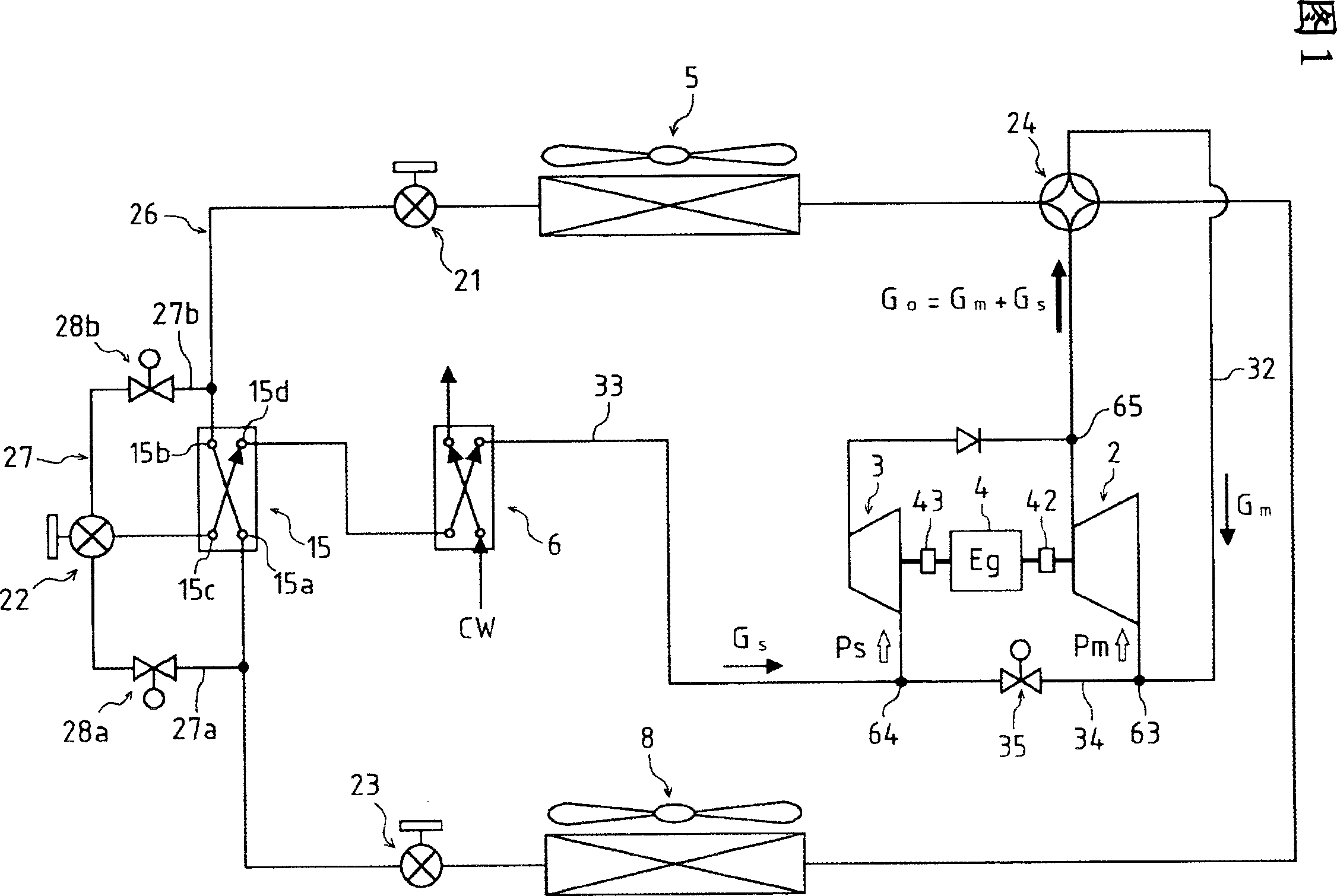
[0031] First, the refrigerant circuit structure and refrigerant cycle of the engine heat pump according to the present invention will be described with reference to FIG. 1 .

[0032] The engine heat pump according to the present invention includes: a main compressor 2 driven by an engine 4, an auxiliary compressor 3, an indoor heat exchanger 8, an outdoor heat exchanger 5, an expansion valve 23 for the indoor heat exchanger, and an expansion valve for the outdoor heat exchanger 21, and the supercooling heat exchanger 15, the supercooling heat exchanger 15 is arranged in the main path 26 as the liquid refrigerant passing path among the connecting paths between the indoor heat exchanger 8 and the outdoor heat exchanger 5, and utilizes The liquid refrigerant for subcooling branched into the branch path 27 (27a, 27b) subcools the liquid refrigerant before branching. The engine heat pump utilizes the refrigerant cycle constituted by the above-mentioned parts. In addition, the subco...


PUM


Abstract

An object of the invention is to provide an engine heat pump whose compression work is reduced without increase of consumed electric power, thereby improving its driving efficiency (energy efficiency). An engine heat pump comprises: an engine (4); a main compressor (2) driven by the engine (4); a sub compressor (3); an indoor heat exchanger (8); an outdoor heat exchanger (5); an expansion valve (23) for the indoor heat exchanger; an expansion valve (21) for the outdoor heat exchanger; and a supercooling heat exchanger (15) disposed on a liquid refrigerant passage (main passage 26) of a connection passage between the indoor heat exchanger (8) and the outdoor heat exchanger (5). In the supercooling heat exchanger (15), a supercooling liquid refrigerant branched into a branching passage (27(27a, 27b)) supercools a liquid refrigerant before being branched. The sub compressor (3) is driven by the engine (4) so as to compress the supercooling liquid refrigerant. A ratio (R) of a capacity of the sub compressor (3) to a total capacity of the main compressor (2) and the sub compressor (3) ranges between 20% and 29%.

Description

technical field [0001] The present invention relates to a device structure of an engine heat pump, and more specifically, relates to a technique for reducing total compression work without increasing new power consumption. Background technique [0002] Regarding an engine heat pump in which an engine drives a compressor, the structure described in Patent Document 1 is known. In Patent Document 1, an invention is disclosed that divides the compression work of the engine heat pump into two systems of compression work produced by the main compressor and that produced by the auxiliary compressor, by dividing one side (the auxiliary compressor side) at a higher pressure than the other side (main compressor side), reducing the compression work on said side, thereby reducing the total compression work in the engine heat pump. [0003] In the aforementioned Patent Document 1, a structure is disclosed in which an electrically driven compressor (electric compressor) is used to perfor...

Claims


Application Information

Patent Timeline
IPC IPC(8): F25B1/00F25B27/00F25B31/00F25B1/10F25B41/00
CPCF25B2400/13F25B27/00F25B41/00F25B1/10F25B2400/0751
Inventor 南健一福留二朗东洋志山中圭史吴服荣太
Owner YANMAR CO LTD
Why Eureka
Try Eureka