Amplifier, correction method for processing time shift and correction system

一种处理时间、放大器的技术,应用在校正系统领域,能够解决没有公开自动测量自动校正、无法应用普通用户音频/视频放大器等问题,达到克服时间差的效果

Inactive Publication Date: 2007-05-02
YAMAHA CORP
View PDF2 Cites 9 Cited by
  • Summary
  • Abstract
  • Description
  • Claims
  • Application Information

AI Technical Summary

Problems solved by technology

However, this document only discloses the measurement technique and does not disclose the technology of automatically measuring the difference and automatically correcting the difference
Therefore, the technology in this document cannot be applied to audio / video amplifiers used by ordinary users

Method used


Image

  • Amplifier, correction method for processing time shift and correction system
  • Amplifier, correction method for processing time shift and correction system
  • Amplifier, correction method for processing time shift and correction system

Examples


Embodiment Construction

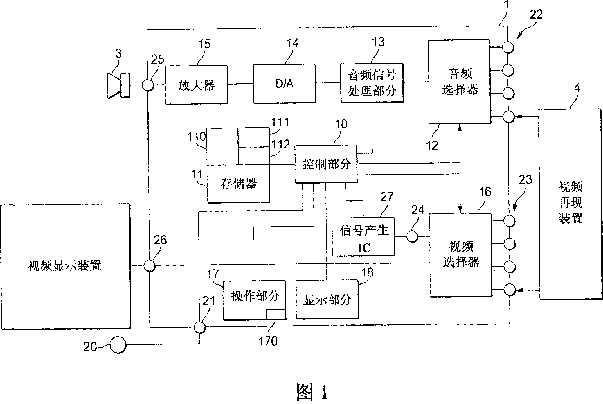
[0040] FIG. 1 is a block diagram of an AV (audio / video) amplifier according to a first embodiment of the present invention.

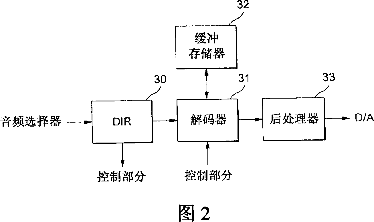
[0041] Fig. 2 is a block diagram of an audio signal processing section of the AV amplifier.

[0042] This AV amplifier 1 has a plurality (4) of audio input terminals 22 and a plurality (4) of video input terminals 23, and any one of them is selected by an audio selector 12 and a video selector 16, respectively. The audio selector 12 and the video selector 16 are switched according to a signal from the control section 10 .

[0043] A video reproduction device 4 such as a DVD player is connected to the audio input terminal 22 and the video input terminal 23 .

[0044] The video signal selected by the video selector 16 is input to the video display device 2 through the video output terminal 26 . This video display device 2 is a PDP (Plasma Display Panel), a DLP (Micromirror Projector), or the like.

[0045] In addition to the four external video input t...


PUM


Abstract

There is provided an amplifier that measures a display delay time caused until a video is displayed actually after a video signal is generated, and sets automatically a delay time of an audio signal such that an audio synchronizes with this display. Test video data is stored in a memory 11. This test video data is video data that generates a clear change in luminance in such a manner that a screen is changed suddenly from deep black to pure white. This test video is output to a video display device 2 such as PDP, for example, and a delay time generated until the test video is displayed actually after this test video is output is measured. Since the luminance of the screen is changed suddenly when the test video is displayed actually, this change can be sensed by an optical sensor 20. The audio signal is delayed by setting this delay time in an audio signal processing portion 13, so that the video can synchronize with the audio.

Description

technical field [0001] The present invention relates to an amplifier, a correction method and a correction system capable of correcting a difference between video and audio caused when an audio / video source is reproduced. Background technique [0002] With the development of high-definition television broadcasting and home theater systems, large-sized display devices such as PDP (Plasma Display Panel), DLP (Micro Mirror Projector), etc. have been put into practical use. However, large-scale display requires processing such as digitizing the input video signal into a dot matrix. Therefore, a delay (display delay time) caused after a video signal is input until it is actually displayed on the screen is large, so that a delay of about 1 to 2 frames (1 / 30 to 1 / 15 second) occurs. [0003] Conversely, in processing such as expanding a compressed digital signal and then converting the expanded digital signal into an analog signal, audio signals also require a predetermined time, b...

Claims


Application Information

Patent Timeline
Patent Type & Authority Applications(China)
IPC IPC(8): H04N5/60H04N5/04H04N17/04
CPCH04N21/4307H04N5/04H04N17/04H04N21/43072
Inventor 前垣宏亲
Owner YAMAHA CORP
Why Eureka
Try Eureka