Track type moveable light steel keel
A light steel keel and track-type technology, applied in the field of light steel keel, can solve the problems of immovability, difficult construction, time-consuming and labor-intensive, etc., achieve compact and perfect installation, save construction time, and improve work efficiency.
- Summary
- Abstract
- Description
- Claims
- Application Information
AI Technical Summary
Problems solved by technology
Method used
Image
Examples
Embodiment 1
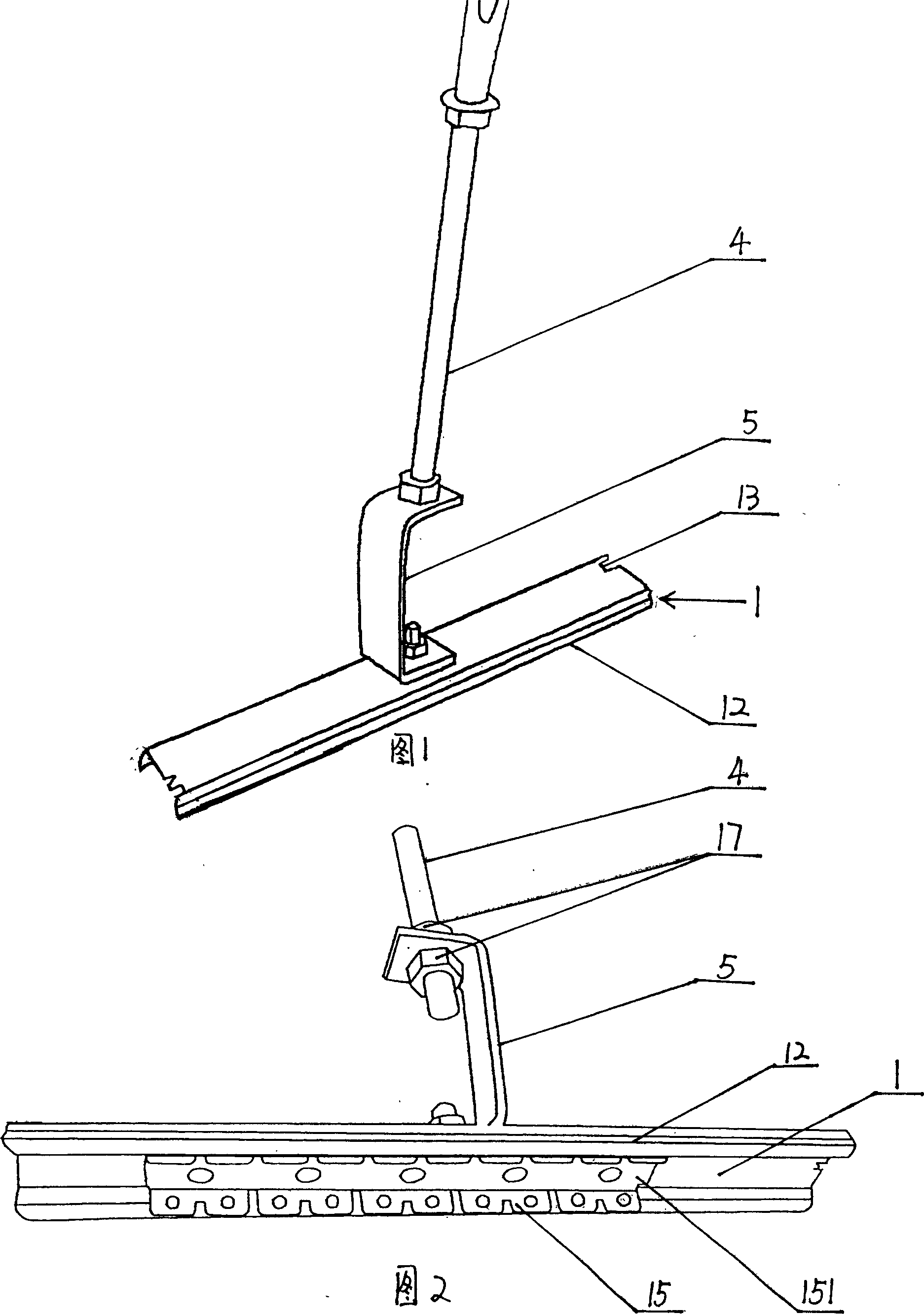
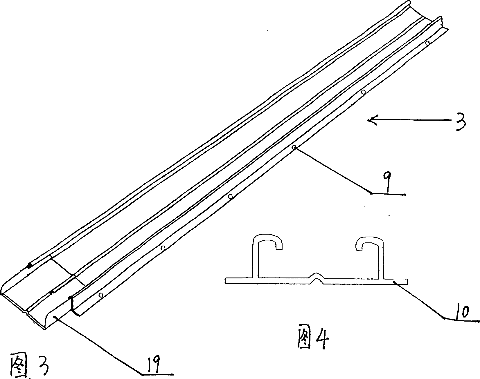
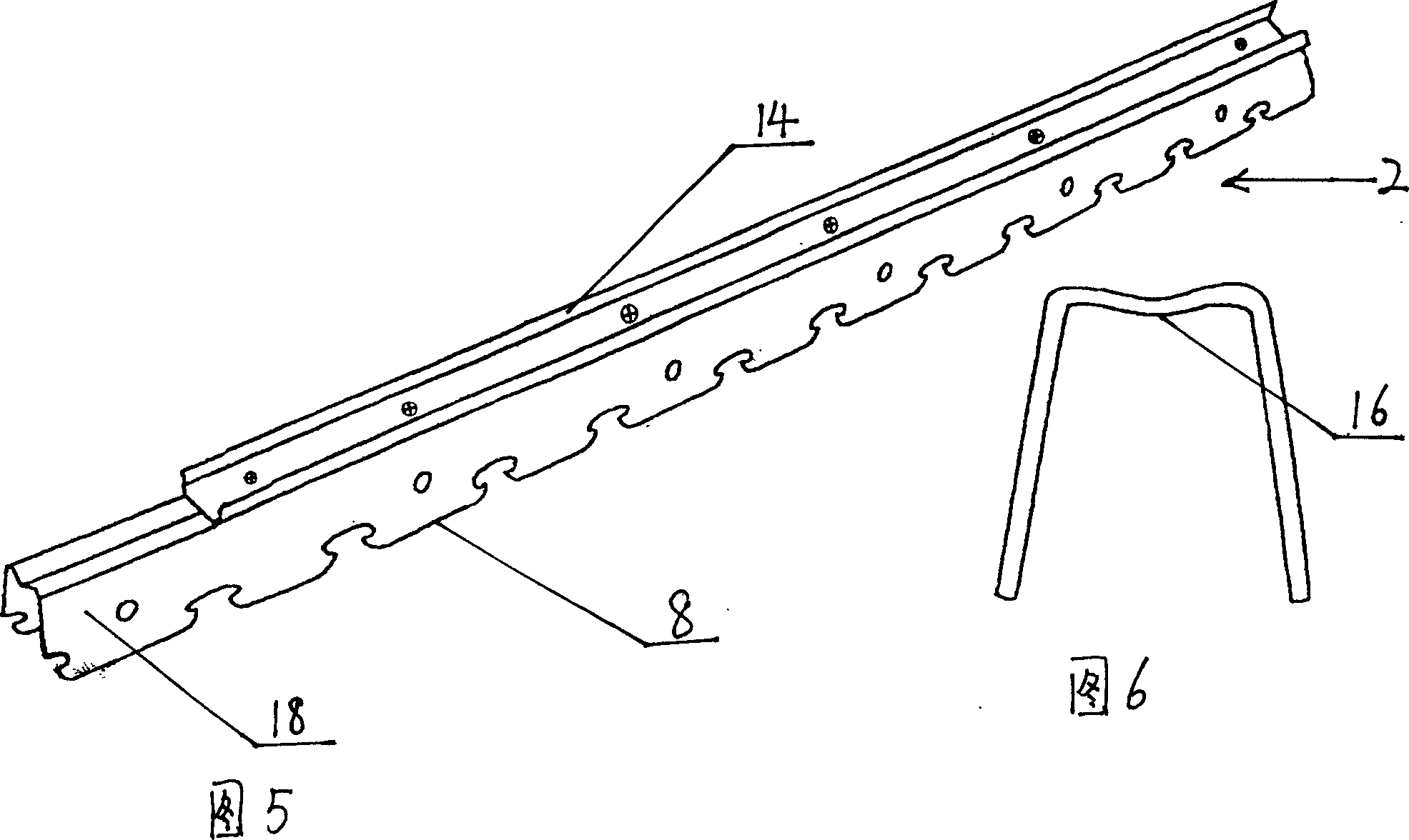
[0030] As shown in Figures 1 to 6 and Figure 11, the track-type movable light steel keel of this embodiment includes an upper keel 1, a lower keel 2, an auxiliary keel 3, a boom 4 and a horizontal adjustment code 5, and the upper keel 1 is a drawer-type slide rail structure, and the lower keel 2 is a "冂" type snap-in lower keel. The drawer-type slide rail structure includes a fixed rail 12, a movable rail 14, and a fixed rail 12 and a movable rail 14. For the ball seat 15 of the ball, a stopper 13 protrudes downward on the flat surface of the fixed rail 12 adjacent to the open end, and the movable rail 14 is installed on the flat surface of the lower keel 2, and the straight surface 151 of the ball seat and the stopper 13 mutually abut , preventing the bead seat 15 from slipping out from the ends of the two sliding tracks; the length of the upper keel 1 is less than the length of the lower keel 2; one end of the lower keel 2 is butted with a keel connector 18, and the The widt...
Embodiment 2
[0034] As shown in Fig. 3, Fig. 4, Fig. 7-10, and Fig. 12, the track-type movable light steel keel of this embodiment includes an upper keel 1, a lower keel 2, an auxiliary keel 3, a boom 4 and a horizontal adjustment code 5 , the upper keel 1 includes a fixed end surface 11 and an inverted T-shaped slide plate 6 fixed below the fixed end surface 11, wherein six hanging holes 20 are provided on the fixed end surface 11; the lower keel 2 is a clip-type lower The keel, which includes a semi-I-shaped hollow chute 7 and a row of hooks 8 fixed on the lower end surface of the chute 7, the inverted T-shaped slide plate 6 of the upper keel 1 slides from the half-I-shaped hollow of the lower keel 2 The openings on both sides of the groove 7 are embedded in the semi-I-shaped hollow chute 7, so that the lower keel 2 can slide relative to the upper keel 1; the length of the upper keel 1 is less than or equal to the length of the lower keel 2.
[0035] The suspender 4 is a long pole with t...
Embodiment 3
[0038] The difference between this embodiment and Embodiment 2 is that there are two rows of hooks (not shown in the figure) on the lower end surface of the hollow chute.
PUM
 Abstract
Description
Claims
Application Information
 - R&D
- Intellectual Property
- Life Sciences
- Materials
- Tech Scout
- Unparalleled Data Quality
- Higher Quality Content
- 60% Fewer Hallucinations
Browse by: Latest US Patents, China's latest patents, Technical Efficacy Thesaurus, Application Domain, Technology Topic, Popular Technical Reports.
© 2025 PatSnap. All rights reserved.Legal|Privacy policy|Modern Slavery Act Transparency Statement|Sitemap|About US| Contact US: help@patsnap.com


