
Low level, heating power deaerator

A thermal deaeration and deaerator technology, applied in chemical instruments and methods, steam separation devices, liquid degassing, etc., can solve the problems of water pump cavitation, small pressure head, waste of energy and water resources, etc., to avoid steam Corrosion, improve utilization, promote the effect of heating

Inactive Publication Date: 2010-05-12
李树生
View PDF7 Cites 0 Cited by
  • Summary
  • Abstract
  • Description
  • Claims
  • Application Information

AI Technical Summary

Problems solved by technology

The defect of the atmospheric deaerator is that the exhaust pipe is directly connected to the external atmospheric environment, and part of the steam in the degassing tower is directly discharged into the atmosphere, resulting in waste of energy and water resources, and due to the low pressure in the water tank, the pressure head in front of the pump is caused Small, easy to form cavitation to the pump

Method used


Image

  • Low level, heating power deaerator
  • Low level, heating power deaerator

Examples


Embodiment Construction

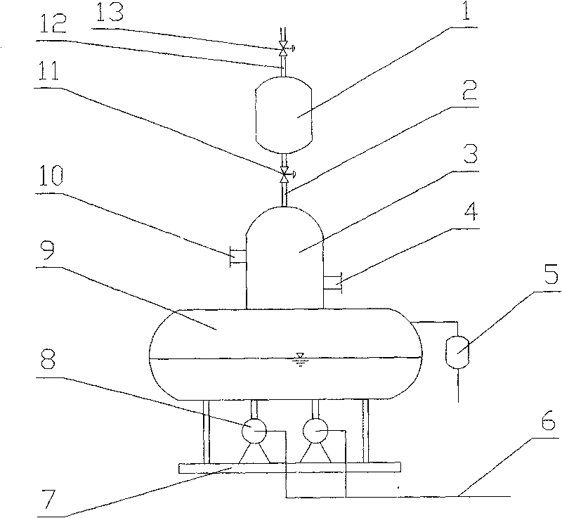
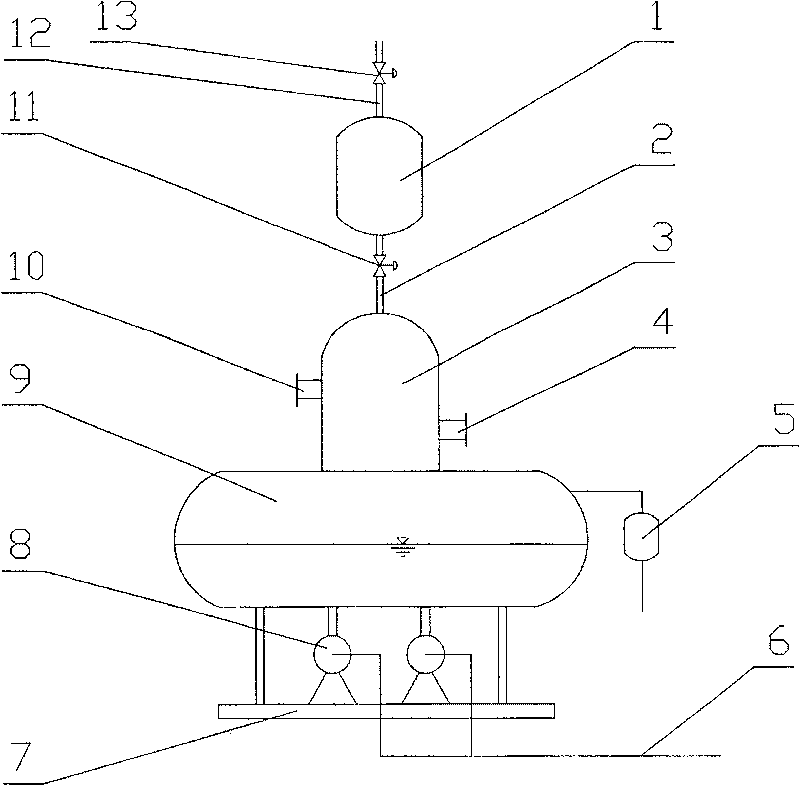
[0007] Referring to the accompanying drawings, a low-level thermal deaerator includes a deaerator body composed of a degassing tower 3 and a water tank 9. The degassing tower is provided with a steam inlet pipe 10, a water inlet pipe 4 and an exhaust pipe 2. The exhaust pipe is connected to the buffer tank 1.

[0008] The exhaust pipe is provided with a valve 11, which can be a normally open electric control valve. Under normal conditions, the steam in the degassing tower directly enters the buffer tank through its exhaust pipe, the exhaust valve of the buffer tank is closed, and the steam is not discharged outside, thus creating pressure in the buffer tank and the degassing tower. When the pressure reaches a certain value, close the exhaust pipe valve of the degassing tower, open the exhaust valve of the buffer tank to discharge the oxygen and non-condensable gas in the buffer tank, then close the exhaust valve of the buffer tank, and open the exhaust valve of the degassing t...


PUM


Abstract

A deaerator of low-level heat power consists of degassing tower and water box. It is featured as setting air inlet pipe, water inlet pipe and air exhaust pipe on degassing tower; connecting one sparewater pump and one on-service water pump to bottom of degassing tower; setting rotary diaphragm, packing and reboiling pipe net in degassing tower; and arranging self-control overflow unit of liquid level on water box.

Description

technical field [0001] The invention relates to a low-level thermal deaerator, which can be mainly used for matching with a steam boiler. Background technique [0002] At present, the deaerator used in the steam boiler is a high-level thermal deaerator, including a deaerator body and a water pump. The deaerator body is composed of a deaeration tower and a deaeration water tank connected to each other. The steam inlet pipe, water inlet pipe and direct exhaust pipe are used for steam inlet, water inlet and exhaust respectively. The defect of the atmospheric deaerator is that the exhaust pipe is directly connected to the external atmospheric environment, and part of the steam in the degassing tower is directly discharged into the atmosphere, resulting in waste of energy and water resources, and due to the low pressure in the water tank, the pressure head in front of the pump is caused Small, easy to form cavitation to the pump. Contents of the invention [0003] In order to...

Claims


Application Information

Patent Timeline
Patent Type & Authority Patents(China)
IPC IPC(8): F22D1/50F22B37/26
Inventor 李树生
Owner 李树生
Learn More