Liquid crystal display faceplate device, and tape coiling type encapsulation for the liquid crystal display faceplate device

A liquid crystal display panel, display panel technology, applied in the direction of instruments, nonlinear optics, optics, etc., can solve the problems of pin lifting, time and material cost consumption, electrical damage of liquid crystal display panel, etc.

Inactive Publication Date: 2007-05-09
高智发明基金第82有限责任公司
View PDF0 Cites 5 Cited by
  • Summary
  • Abstract
  • Description
  • Claims
  • Application Information

AI Technical Summary

Problems solved by technology

In the latter part of the assembly process, it is a part of the process where on-site operators are relatively concentrated. The tape and reel packaging 94 connected between the long side 931 of the liquid crystal display panel 93 and the source driver printed circuit board 91, especially the adjacent The two tape-and-reel packages 95 and 96 at the two ends of the long side 931 are likely to be bumped due to personnel negligence in the back-end process, so that the pins 942 are lifted, and the left and right ends of the long side 931 of the liquid crystal display panel 93 are damaged after completion. Bright line (open line) appears in the test of the segment process
[0005] Although there are protruding substrates 948 to protect the left and right sides of the contact areas 946, 947, so that in the contact areas 946, 947, the pins 942 on the most left and right sides will not be directly impacted from the side. The protruding substrate 948 is connected to the substrate 941 of the contact areas 946, 947. When the protruding substrate 948 is lifted by an external force, it will still move the substrate 941 of the contact areas 946, 947, and also make the substrate 941 connected to the substrate 941 The pin 942 is lifted up and separated from the source driver printed circuit board 91 or / and the electrode 933 of the liquid crystal display panel 93, and causes the generation of bright lines
This will not only cause electrical damage to the liquid crystal display panel 93, but also result in time and material costs due to the need to replace defective products.

Method used


Image

  • Liquid crystal display faceplate device, and tape coiling type encapsulation for the liquid crystal display faceplate device
  • Liquid crystal display faceplate device, and tape coiling type encapsulation for the liquid crystal display faceplate device
  • Liquid crystal display faceplate device, and tape coiling type encapsulation for the liquid crystal display faceplate device

Examples


Embodiment Construction

[0035] The aforementioned and other technical contents, features and effects of the present invention will be clearly presented in the following detailed description of preferred embodiments with reference to the drawings.

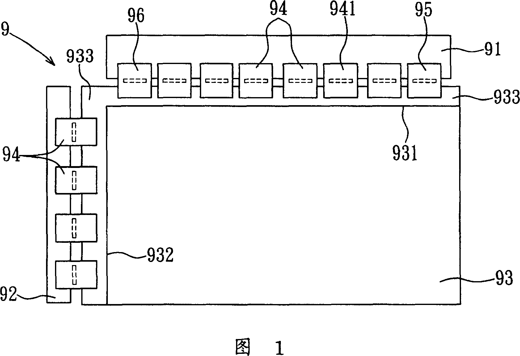
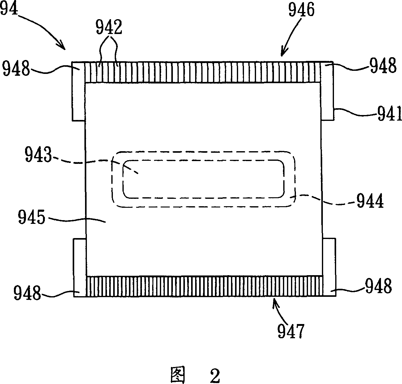
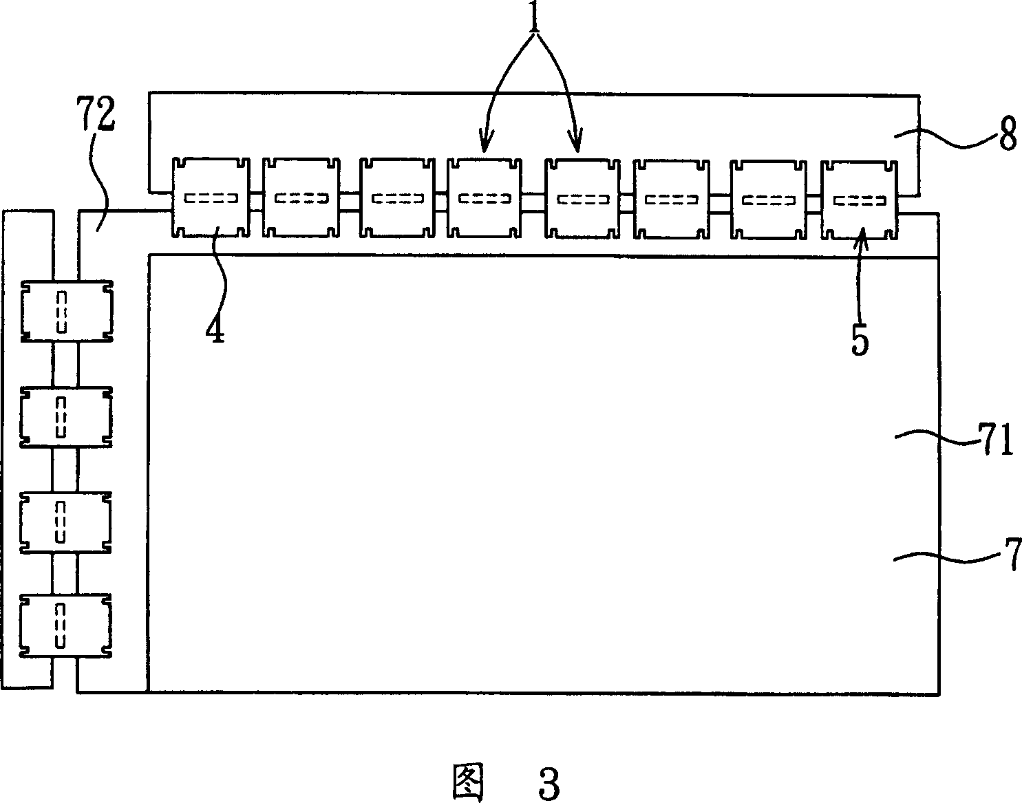
[0036]Referring to FIG. 3 , FIG. 4 and FIG. 5 , a preferred embodiment of the liquid crystal display panel device of the present invention includes a driving printed circuit board 8 , a display panel 7 and a plurality of tape and reel packages 1 . The display panel 7 has a display area 71 and a conducting area 72 located at a side of the display area 71 . Each tape and reel package 1 includes a substrate 11 , a chip 12 , a plurality of pins 13 , a solder resist layer 14 and a sealing material 15 . The substrate 11 is made of flexible insulating material, and defines a front end 61, a rear end 62, a left side 63 and a right side 64. A dummy area 112, and a wire area 111 located between the dummy pressing area 112, and the wire area 111 forms a first contac...


PUM


Abstract

A liquid crystal display unit consists of a driving printed circuit; a display face plate connected separately to driving printed circuit and to multiple winding type of package including base plate with multiple false pressed region at left and right sides, the first contact region, the second contact region and multiple open unit for avoiding electric damage caused by pin in contact region when pin is lifted up by false pressed region.

Description

technical field [0001] The invention relates to a tape-and-roll package, in particular to a tape-and-roll package for electrically connecting a driving printed circuit board and a display panel in a liquid crystal display panel device. Background technique [0002] Referring to FIG. 1 , generally in a panel device 9 of a thin film transistor liquid crystal display (Thin FilmTransistor Liquid Crystal Display, referred to as TFT-LCD), a source driver print circuit board 91 (source driver print circuit board) which drives a source line (source line) ) and a gate driver print circuit board 92 (gate driver print circuit board) for driving gate lines are placed on the long side 931 and the short side 932 of the liquid crystal display panel 93 respectively and are separated from the liquid crystal display panel 93 by a certain distance. The tape carrier packages 94 (Tape carrier packages, TCP for short) are used to electrically connect the liquid crystal display panel 93 and the so...

Claims


Application Information

Patent Timeline
Patent Type & Authority Applications(China)
IPC IPC(8): G02F1/1333
Inventor 陈伯龙
Owner 高智发明基金第82有限责任公司
Why Eureka
Try Eureka