Parking brake device

A braking device and parking technology, which is applied to the types of brakes, brake components, brake actuators, etc., and can solve problems such as increased power consumption and complex structures

Inactive Publication Date: 2007-05-09
HONDA MOTOR CO LTD +1
View PDF2 Cites 7 Cited by
  • Summary
  • Abstract
  • Description
  • Claims
  • Application Information

AI Technical Summary

Problems solved by technology

However, it is necessary to store the electromagnet in the brake caliper, which not only complicates the structure, but also must maintain the energized state of the winding of the electromagnet in the parking brake state, so the power consumption increases

Method used


Image

  • Parking brake device
  • Parking brake device
  • Parking brake device

Examples


Embodiment 1

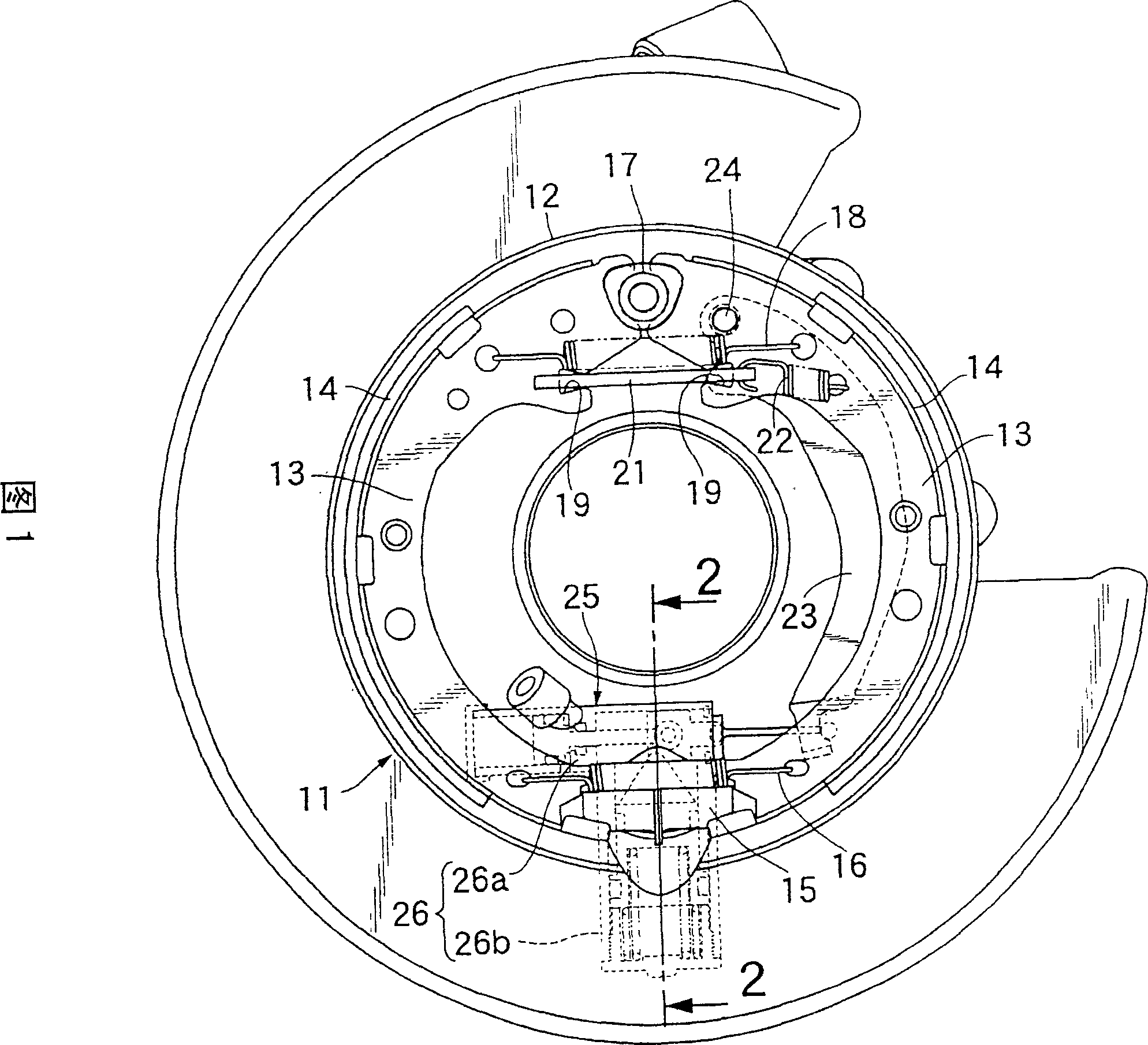
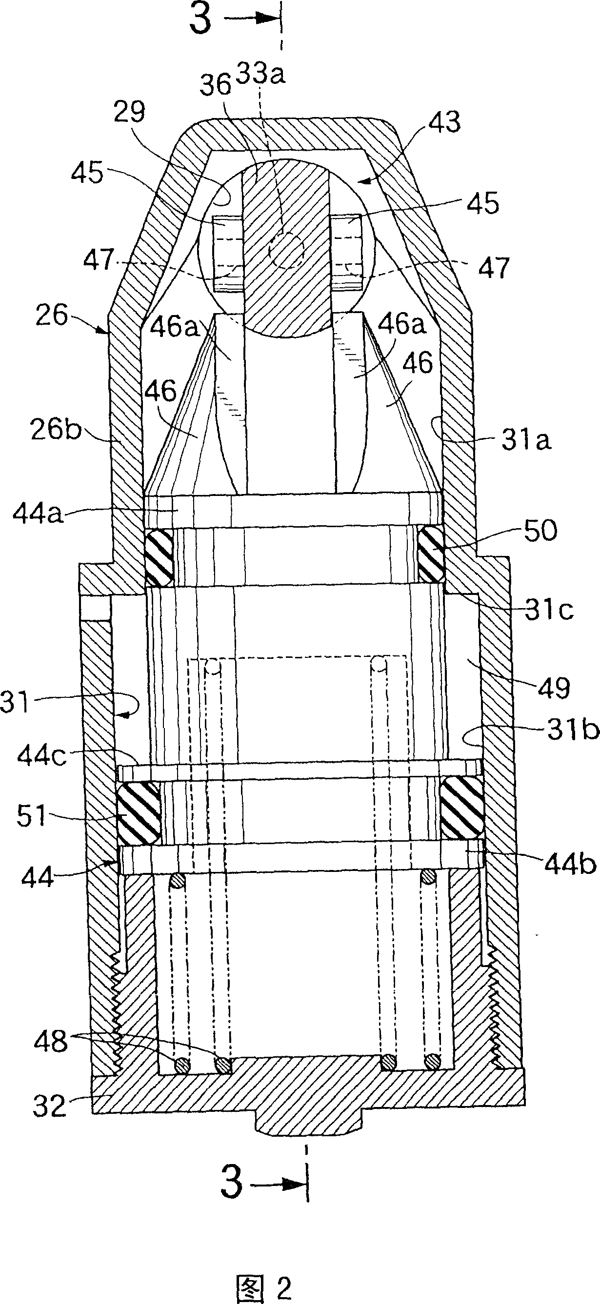
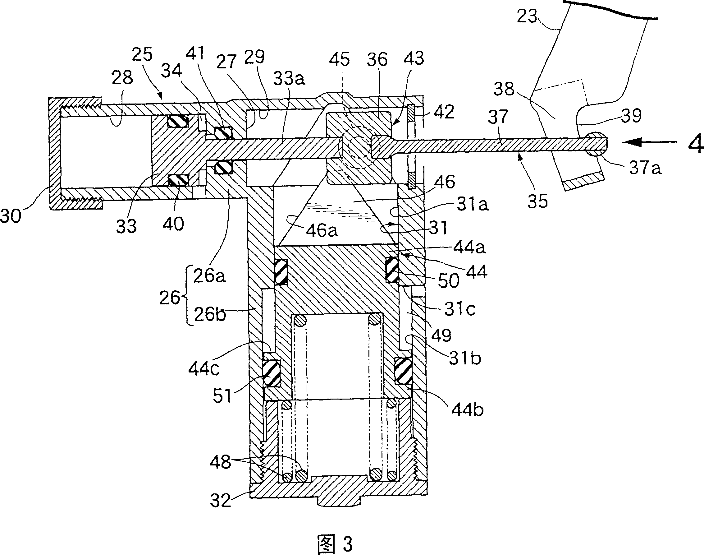
[0023] 1 to 9 show an embodiment of the present invention.

[0024] First, in FIG. 1 , a base plate 12 included in a drum brake 11 , which is a brake mechanism exclusively for parking brakes, covers an open end of a not-shown brake drum and is fixedly mounted on the vehicle body side. There are brake linings 14, 14 that can be slidably connected with the above-mentioned brake drum, and one end of a pair of brake shoes 13, 13 arranged in the brake drum can be swingably supported on the two ends of the telescopically adjustable pillar 15 , Between one end of the two brake shoes 13..., a spring 16 compressing the two brake shoes 13... In addition, the other ends of the two brake shoes 13 are detachably supported by anchors 17 provided on the base plate 12, and are biased toward the side supported by the anchors 17 via return springs 18. In addition, notches 19 are respectively provided on the opposing surfaces of the other end sides of the two brake shoes 13..., and the two ends...


PUM


Abstract

A parking brake device arranged so that a parking brake state is obtained by the operation of forwarding a parking piston (33) in response to the action of a parking control liquid pressure, while the forwarding state of the parking piston (33) is mechanically locked by a lock mechanism (43). Furthermore, the input member (23) of a brake mechanism (11) and the parking piston (33) are connected by a connecting means (35). A piston (44) possessed by the lock mechanism (43) is actuated in one axial direction at the time of the operation of forwarding the parking piston (33), so that a lock section (46) provided at one end of the lock piston (44) engages an engaging section (45) from behind while standing astride the intermediate section of the connecting means (35), which engaging section (45) is disposed in the intermediate section of the connecting means (35). This makes it possible to obtain an automatic parking brake state by a simple construction not involving electric power consumption.

Description

technical field [0001] The invention relates to a parking brake device, in particular to a parking brake device which obtains a parking brake state through hydraulic action. Background technique [0002] Such a parking brake device is known, for example, in Patent Document 1, Patent Document 2, and the like. [0003] Patent Document 1: Japanese Special Application Form No. 10-512947 [0004] Patent Document 2: Japanese Special Publication No. 2000-504811 [0005] However, in the aforementioned Patent Document 1, the brake piston is divided into a front brake piston and a rear brake piston, and at the same time, the transmission member that contacts the front end of the rear brake piston and the blocking plate fixed to the front brake piston A spring is compressed between them, and the pawl, which can be engaged with the internal teeth engraved on the inner surface of the brake caliper behind the front brake piston, is in contact with the front end of the rear brake piston ...

Claims


Application Information

Patent Timeline
Patent Type & Authority Applications(China)
IPC IPC(8): F16D65/24F16D65/18F16D65/14F16D65/22
CPCF16D2129/02F16D2121/02F16D2127/06F16D65/22
Inventor 稻垣裕巳平塚明良
Owner HONDA MOTOR CO LTD
Why Eureka
Try Eureka