Apparatus for controlling power supply, method and electron system

A power supply control device and power supply technology, applied in the field of circuits, can solve problems such as energy consumption and failure to reach zero power consumption

Inactive Publication Date: 2007-05-16
VIMICRO CORP
View PDF0 Cites 13 Cited by
  • Summary
  • Abstract
  • Description
  • Claims
  • Application Information

AI Technical Summary

Problems solved by technology

Although this method achieves the purpose of intelligent operation of switching on and off, the power domain of the real-time clock in the working state will still consume energy after the shutdown, and the goal of zero power consumption cannot be achieved.

Method used


Image

  • Apparatus for controlling power supply, method and electron system
  • Apparatus for controlling power supply, method and electron system
  • Apparatus for controlling power supply, method and electron system

Examples


Embodiment Construction

[0056] The present invention will be further described in detail below in conjunction with the accompanying drawings.

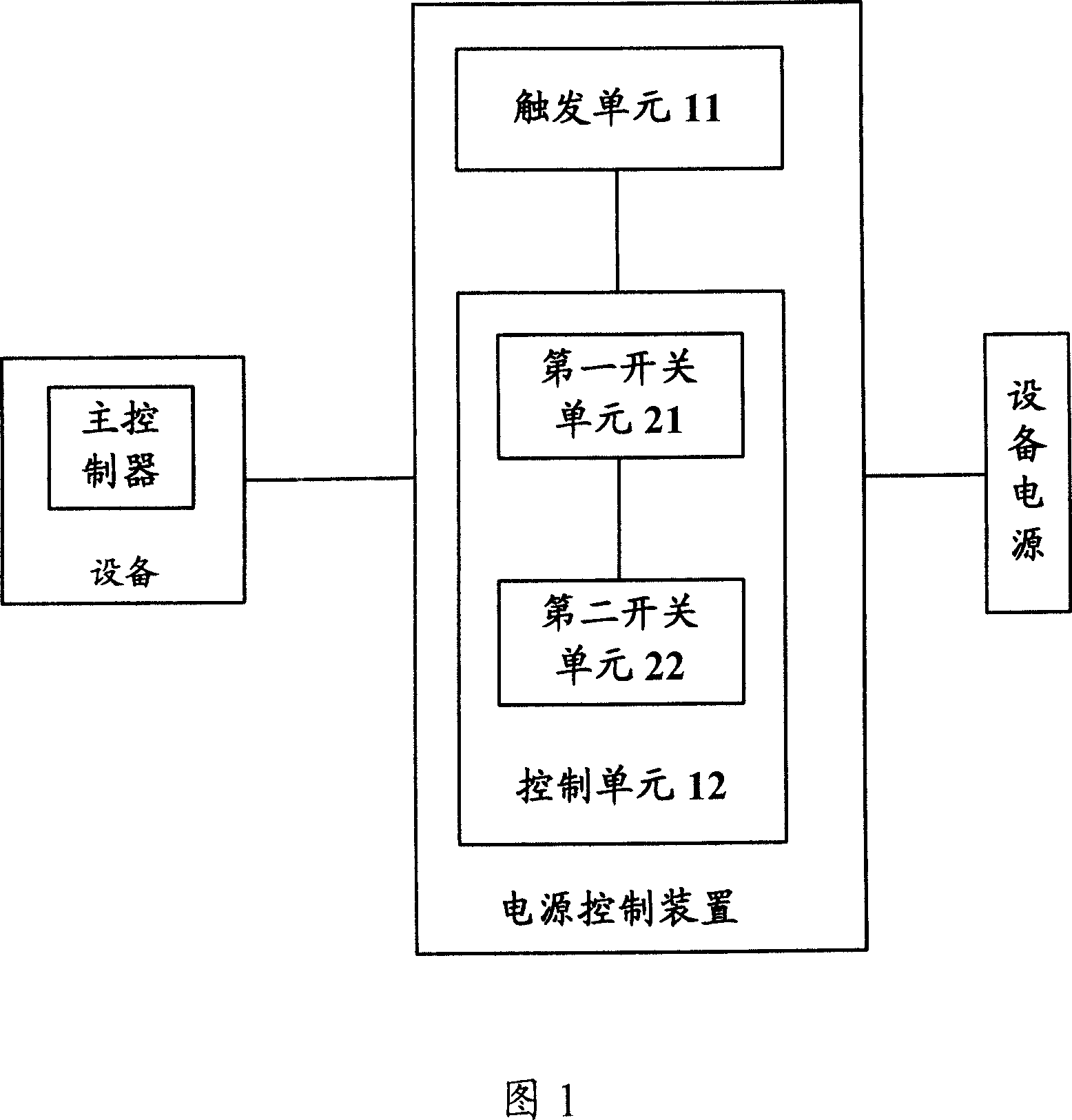
[0057] As shown in FIG. 1 , it is a schematic structural diagram of a power control device of the present invention. The device is located between the device and the device power supply that supplies power to the device. The device includes a trigger unit 11 and a control unit 12 . Wherein, when the device is in the open state, the trigger unit 11 is used to send a trigger signal to the main controller in the device; the control unit 12 is used to switch the The connection between the device and the power supply of the device is disconnected, and the non-enabling signal is sent by the main controller after receiving the trigger signal.

[0058] Further, the disabling signal may be sent by the main controller in the device after receiving the trigger signal and the duration of the trigger signal reaches a preset value.

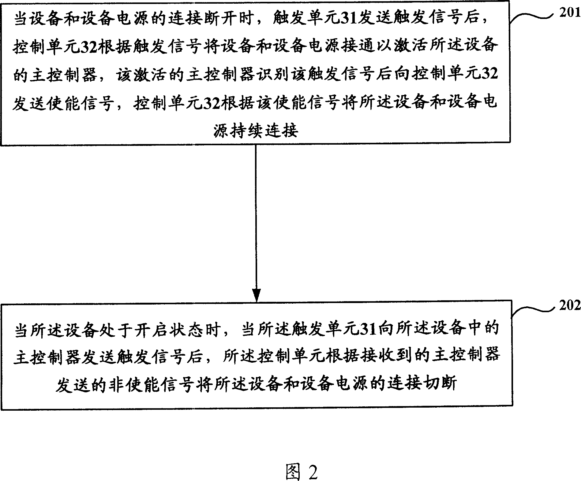
[0059] When the connection between the...


PUM


Abstract

This invention relates to one power control device located between device and power supply device, wherein, the device comprises trigger unit and control unit; when the device is at open status, the said trigger unit is to send trigger signal to the main controller; the said control unit is to receive no signal to break off the device and device power; the no signal is received by main controller to the trigger signal for sending. This invention also discloses one power control method and electron system.

Description

technical field [0001] The present invention relates to the field of circuit technology, and in particular to a power control device and method, that is, an electronic system. Background technique [0002] In an electronic device that uses a DC power supply, especially a battery, the power consumption of the device in a shutdown state is a very important performance index of the device. For example, for electronic devices that use batteries like MP3 or digital cameras, due to the low power consumption or zero power consumption in the off state, energy is saved to extend the battery life, and the performance index of energy consumption of the electronic devices will be greatly improved. . [0003] At present, there are mainly two methods for realizing energy saving in the shutdown state. One method is to add a power switch. When the device is turned off, turn the power switch to the off state, so that the power supply does not supply power to the device at all, and achieve ...

Claims


Application Information

Patent Timeline
Patent Type & Authority Applications(China)
IPC IPC(8): G05B19/04
Inventor 邓乃利
Owner VIMICRO CORP
Why Eureka
Try Eureka