Circuit breaker

A circuit breaker and circuit technology, applied in the direction of circuit breaker components, etc., can solve the problems of prolonging the breaking time, unable to break the circuit, and unable to break the arc with all the arc suppression plates 11, and achieve the effect of improving the current limiting effect.

Active Publication Date: 2007-05-16
MITSUBISHI ELECTRIC CORP
View PDF1 Cites 3 Cited by
  • Summary
  • Abstract
  • Description
  • Claims
  • Application Information

AI Technical Summary

Problems solved by technology

Therefore, all the arc extinguishing plates 11 cannot be used to break off the arc, which sometimes leads to prolonged breaking time or failure to break the circuit.

Method used


Image

  • Circuit breaker
  • Circuit breaker
  • Circuit breaker

Examples


Embodiment approach 1

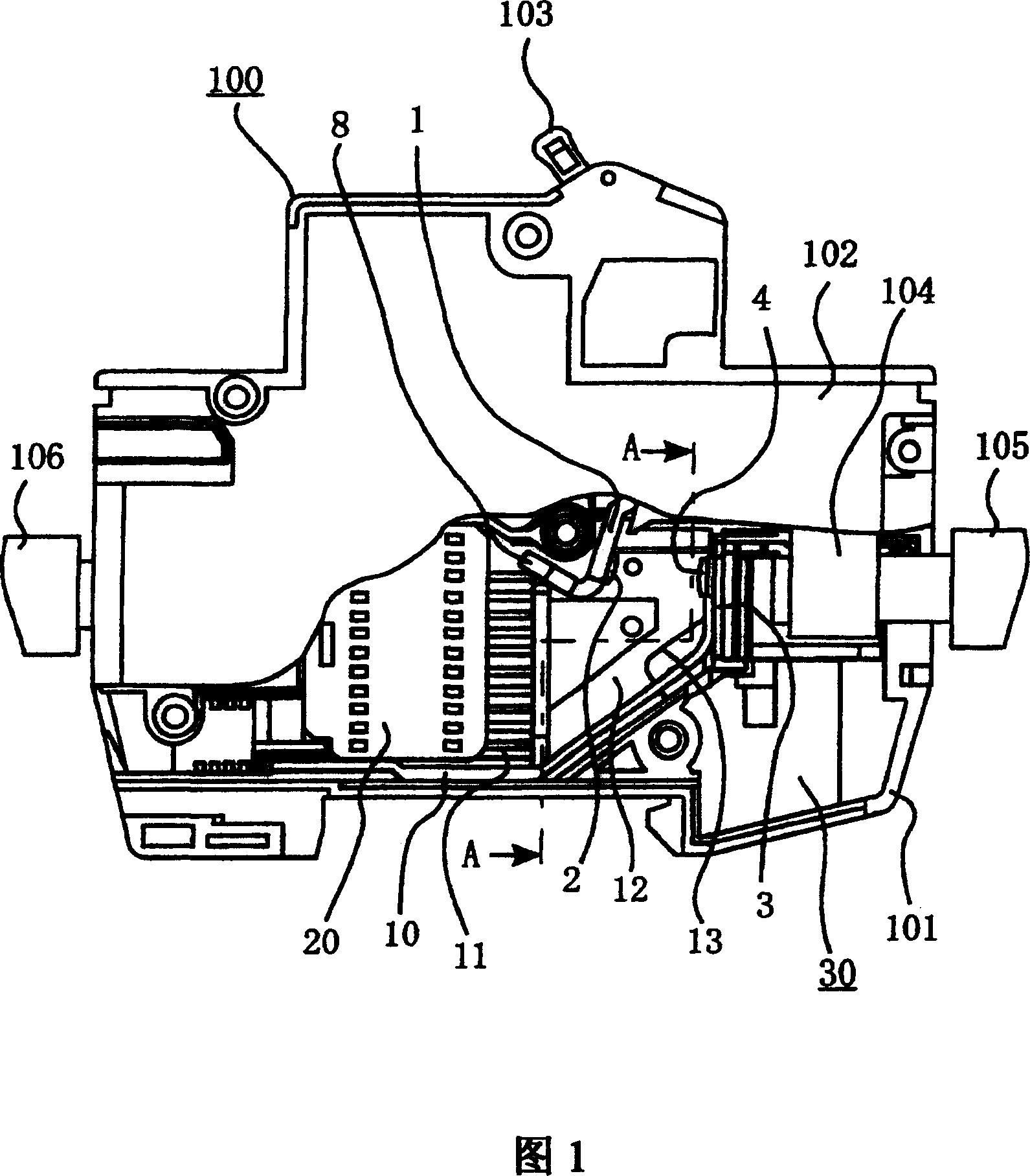
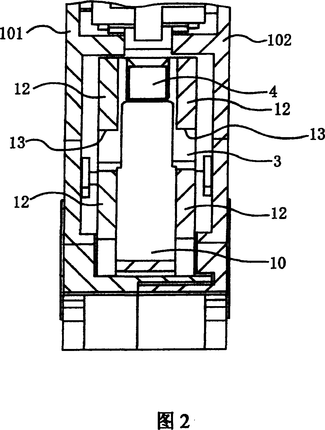
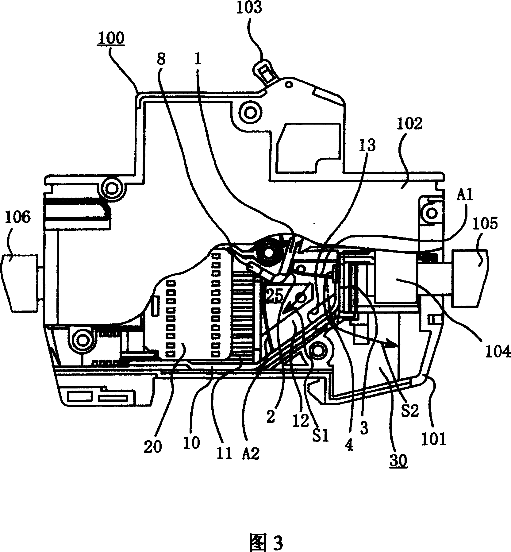
[0023] Fig. 1 is a front view of a circuit breaker in an off state according to Embodiment 1 of the present invention, showing the inside thereof with a part cut away. Fig. 2 is a cross-sectional view along the line A-A in Fig. 1, and the cut-away part in Fig. 1 is also shown for convenience. In addition, FIG. 3 is a front view schematically adding the arc operation and arc flow during the breaking operation to FIG. 1 , and FIG. 4 is an enlarged perspective view of the arc protector used in Embodiment 1 of the present invention.

[0024] In FIG. 1 , a circuit breaker 100 is constituted by an insulating case composed of a base 101 and a case 102 each formed of synthetic resin. An opening and closing mechanism (not shown) is accommodated in the base 101 , and a handle 103 associated with the opening and closing mechanism protrudes from the insulating case and can be operated by hand from the outside, as is well known. In addition, 105 is a power-side conductor connected to the ...

Embodiment approach 2

[0033] Fig. 5 is a partial sectional front view of a circuit breaker according to Embodiment 2 of the present invention, and corresponds to Fig. 1 . In the figure, the parts identical or corresponding to those in FIG. 1 are denoted by the same reference numerals. In FIG. 5 , the discharge hole 14 is provided in a part of the base 101 , and the cooling plate 15 is more preferably provided in the interior thereof, and it is completely the same as that of FIG. 1 . The gas introduced into the arc gas introduction chamber 30 is preferably discharged to the outside through the discharge hole 14 (see FIG. 6 ) provided in the susceptor 101 . The size of the discharge hole 14 can be arbitrarily set within a range in which the exhaust gas discharged from the discharge hole 14 to the outside does not short-circuit to ground due to contact with a metal object existing therearound. In addition, the cooling plate 15 provided inside the discharge hole 14 is used to cool the gas, for example...

Embodiment approach 3

[0035] Fig. 7 shows the circuit breaker in Embodiment 3 of the present invention, (a) is a cross-sectional view along the A-A line in Fig. 1, corresponding to Fig. 2, (b) is a partially enlarged oblique view near its arc flow path, Comparable to Figure 4. In the figure, the same or corresponding parts as those in Fig. 4 are denoted by the same reference numerals. In Embodiment 1 above, when connecting the two chambers of the arc gas introduction chamber 30 and the arc generating chamber 25, the notch 13 for cutting the arc protector 12 is provided. A cutout portion 16 is provided. Therefore, even if a part of the arc runner 10 is cut off, there is no problem as long as the welding characteristics of the arc runner 10 are satisfied.


PUM


Abstract

A circuit breaker can drive the electric arc generated between movable contact-point and fixed contact-point to the direction of arc-suppression device quickly, and can obtain high current limiting performance. The circuit breaker is provided with: an insulation shell body composed of pedestal and shell; a fixed contact component which is installed in the inner of the insulation shell body and has a fixed contact-point in one end; a movable contact component, which has movable contact-point that can contact/separate with the fixed contact-point; an electric arc protection component disposed on the both sides of the fixed contact component; an arc-suppression device which suppresses the electric arc generated when the movable contact component separates from the fixed contact component; and an arc channel, for guiding the arc to the arc-suppression device, provided with a connection unit for connecting the arc generation chamber circled by the electric protection component, arc channel, art-suppression device and the track of the movable contact component with the electric arc gas guide chamber circled by the pedestal, shell, and arc channel, guiding the electric arc gas generated in the electric arc generation chamber to the electric arc gas guide chamber.

Description

technical field [0001] The present invention relates to a circuit breaker, and in particular, relates to improvement of breaking performance of a small circuit breaker used in a household switchboard. Background technique [0002] The circuit breaker not only has the function of opening and closing the circuit by operating the operating handle of the circuit breaker, that is, the so-called switch function, but also has the overcurrent breaking function of cutting off the circuit when an overcurrent such as an overload current or a short circuit current flows. It is an important task to prevent burning of electric wires and load equipment caused by this overcurrent. With the increase of power supply capacity, various companies are trying to figure out how to make the overcurrent breaking function have a greater breaking capacity, but especially in circuit breakers used in households, etc., because of their small size, it is difficult for To improve the breaking capacity, how...

Claims


Application Information

Patent Timeline
Patent Type & Authority Applications(China)
IPC IPC(8): H01H73/18
Inventor 信太秀夫芦刈康宏村田士郎
Owner MITSUBISHI ELECTRIC CORP
Why Eureka
Try Eureka