Autostereoscopic rear projection screen and associated display system

A display system, stereo vision technology, applied in stereo systems, image communication, electrical components, etc., can solve problems such as low efficiency, complex manufacturing, crosstalk, etc.

Inactive Publication Date: 2007-05-16
MICROSHARP CORP LTD
View PDF11 Cites 25 Cited by
  • Summary
  • Abstract
  • Description
  • Claims
  • Application Information

AI Technical Summary

Problems solved by technology

[0013] In this way, various 3D display systems have been developed, but their applications are limited by many factors
These factors include diffraction issues due to parallax aperture, manufacturing complexity, crosstalk, and inefficiencies due to light occlusion

Method used


Image

  • Autostereoscopic rear projection screen and associated display system
  • Autostereoscopic rear projection screen and associated display system
  • Autostereoscopic rear projection screen and associated display system

Examples


Embodiment Construction

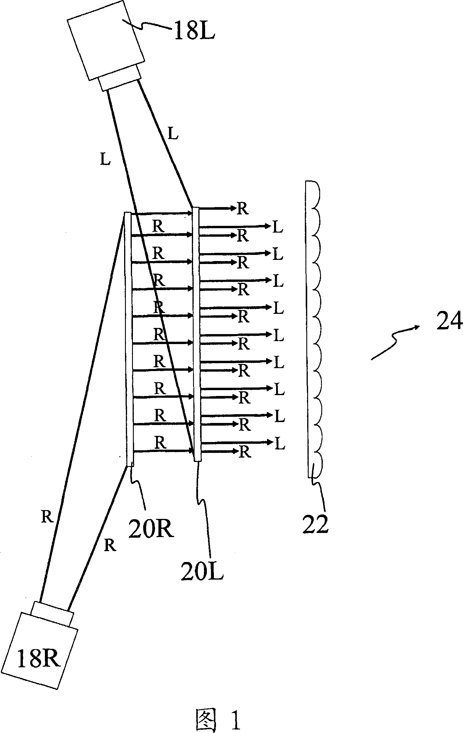
[0070] One aspect of the present invention provides a 3D display system that optically combines a right-eye image with a left-eye image to produce a 3D spatially multiplexed image.

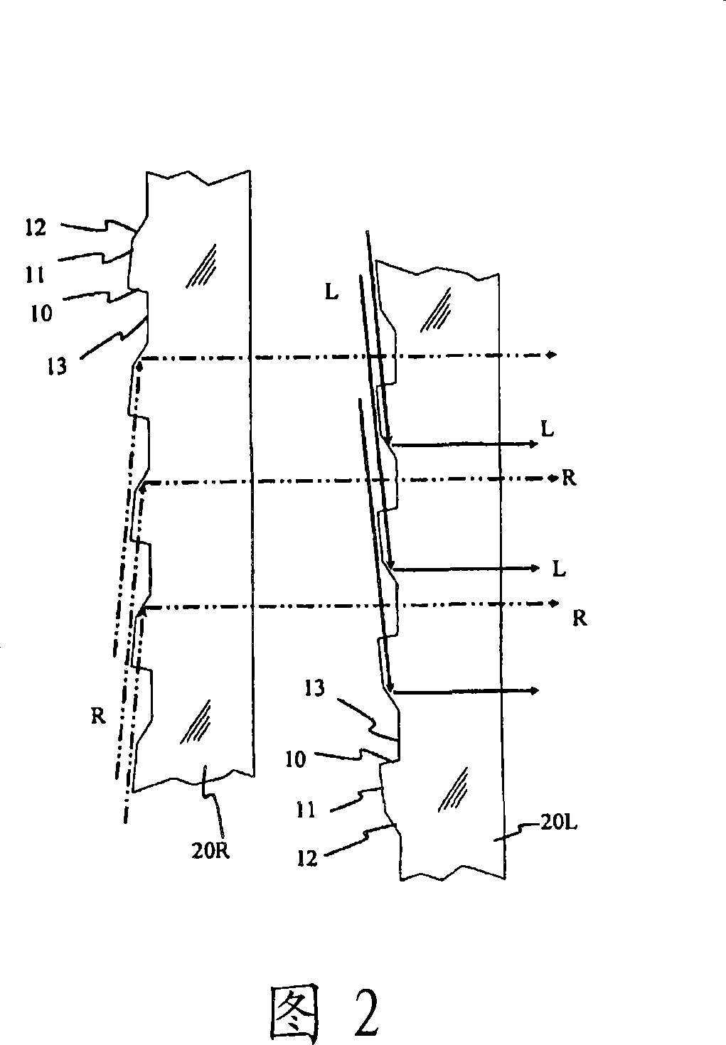
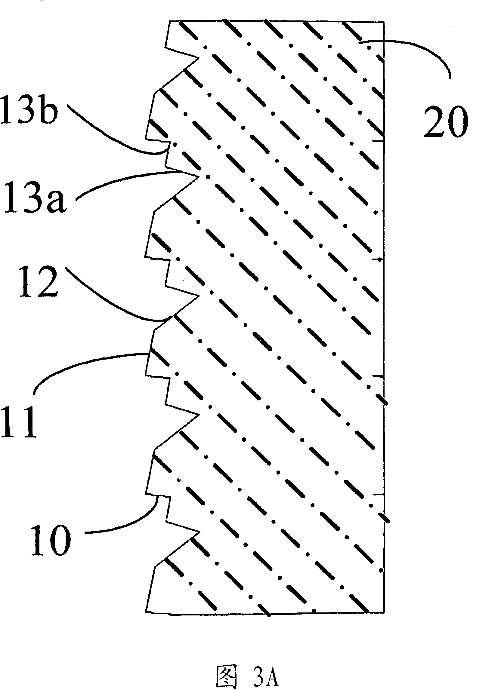
[0071] 1 shows a preferred embodiment of a 3D rear projection display system, which includes a left image projector 18L, a right image projector 18R, a right redirection optical screen 20R, a left redirection optical screen 20L and Convex sheet 22. The right eye image component produced by right image projector 18R is illuminated onto the back of right redirecting optical screen 20R. Thus, it is redirected towards the lenticular sheet 22 and the downstream viewing area 24 . Thus, in addition to the optical screen 20R, the redirected light has to pass through the optical screen 20L to reach the lenticular sheet 22 . Simultaneously, the left eye image component produced by left image projector 18L is illuminated to the back of left redirecting optical screen 20L and redirected in a downstream dire...


PUM


Abstract

The invention discloses an autostereoscopic rear projection screen and associated display system, for displaying an image. The system comprises projection means (18L, 18R) to project first and second stereoscopic image components; a first light-redirecting panel (20R) and a second downstream light-redirecting panel (20L) to receive light representative of the first and second image components, respectively, from the projection means and to redirect that light substantially in a downstream direction, the first and second panels arranged to spatially multiplex the first and second image components; and a parallax optic element (22) located downstream of the second panel to provide at a downstream viewing zone (24) the first and second image components for autostereoscopic viewing of the image. The projection means may be switchable between 2D and 3D viewing modes. A 3D image may be produced by simultaneously or sequentially projecting a series of 2D image sections, using diffuser elements (45). A method of displaying a 3D image is also disclosed.

Description

technical field [0001] The present invention relates to a display system, and more particularly, to an autostereoscopic and volumetric image display system for displaying three-dimensional (3D) images. The present invention concerns a 3D image projection system that does not require the viewer to wear goggles or glasses. Background technique [0002] It is well known in the art that a 3D image can be obtained by combining two images (ie a left eye image and a right eye image) which are then processed by a suitable 3D display system. 3D display systems can be divided into two categories according to the technique used to direct the left and right images to the appropriate eyes: Those 3D display systems that require optics (such as eyes and goggles) close to the viewer's eyes are known as stereopsis display, and those 3D display systems with eye-addressing components fully integrated in the display itself are called autostereoscopic displays. [0003] In the case of an autos...

Claims


Application Information

Patent Timeline
Patent Type & Authority Applications(China)
IPC IPC(8): H04N13/00H04N13/395H04N13/363
CPCH04N13/0454H04N13/0409H04N13/0495H04N13/0443H04N13/0404H04N13/0411H04N13/305H04N13/395H04N13/312H04N13/31H04N13/346H04N13/359H04N13/363
Inventor 萨米尔·梅索阿瑞伊曼·易卜拉欣·孔达卡尔安娜·泰勒·奥尼尔李龙敏
Owner MICROSHARP CORP LTD
Why Eureka
Try Eureka