Support structure for control pedal

A technology for supporting structures and pedals, applied to superstructures, superstructure subassemblies, control components, etc., can solve problems such as the main body of the pedal being stuck on the pedal bracket

Inactive Publication Date: 2007-05-23
MAZDA MOTOR CORP +1
View PDF0 Cites 15 Cited by
  • Summary
  • Abstract
  • Description
  • Claims
  • Application Information

AI Technical Summary

Problems solved by technology

However, the above-mentioned structure has the following problem, that is, when the vehicle collides and the above-mentioned pedal body expands and deforms with the applied impact load, if an oblique load acts on the pedal body supported on the pedal bracket, i

Method used


Image

  • Support structure for control pedal
  • Support structure for control pedal
  • Support structure for control pedal

Examples


Embodiment Construction

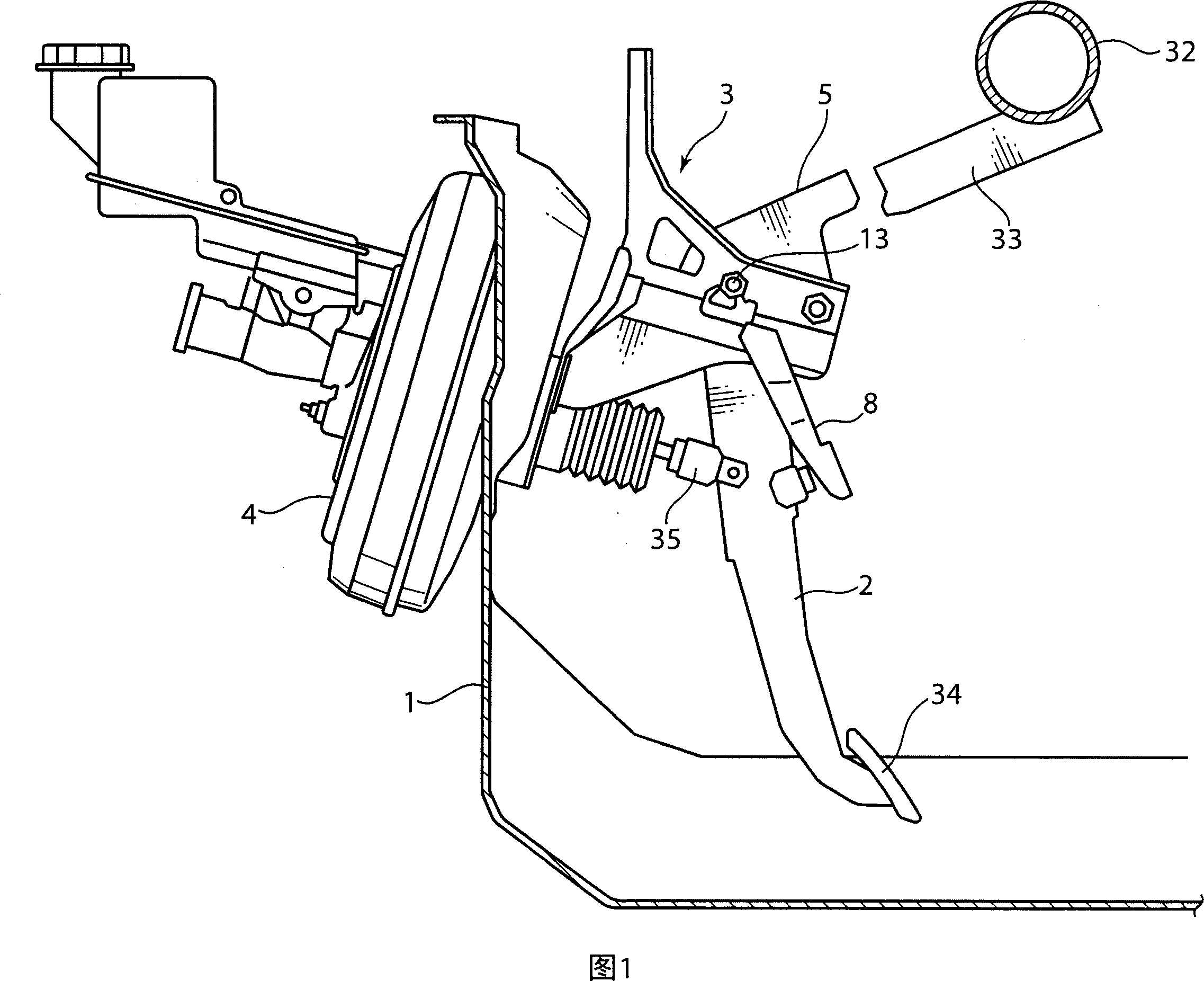
[0121] FIG. 1 shows an operating pedal support structure according to a first embodiment of the present invention. In Fig. 1, 1 denotes the dash panel separating the engine room and the vehicle compartment. On the dash panel 1, a pedal bracket 3 supporting a swingable pedal body 2 constituting an operating pedal such as a brake pedal and a brake booster are installed. 4, and on the above-mentioned pedal bracket 3, the pivot rod 5 that drives the rotation fulcrum of the pedal body 2 to fall off downward when the vehicle collides is supported.

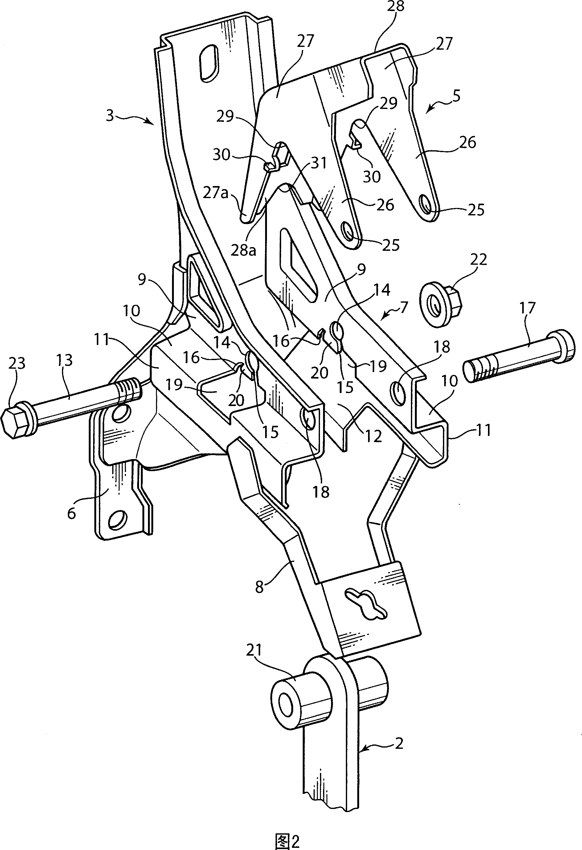
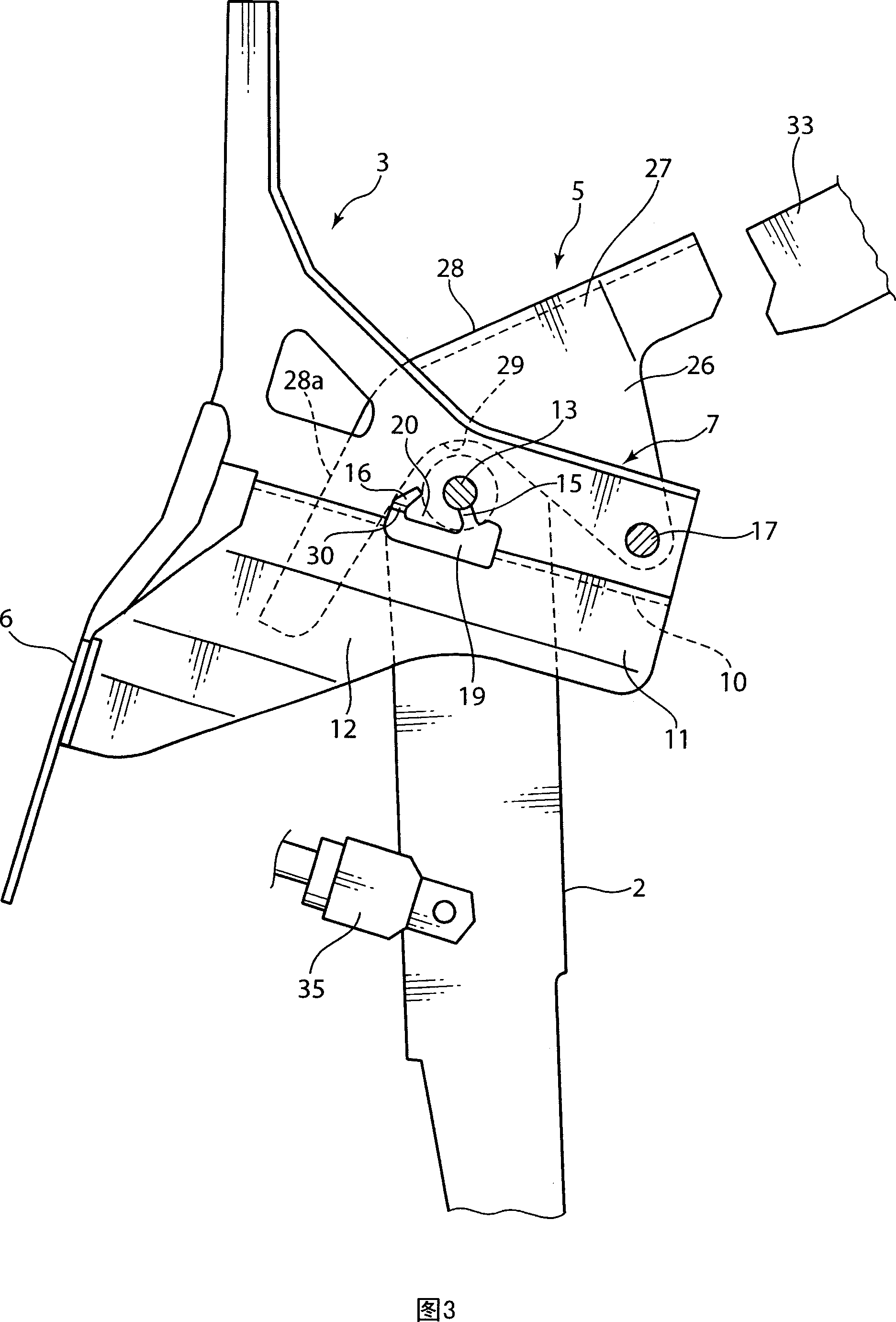
[0122] As shown in Figures 2 to 4, the above-mentioned pedal bracket 3 includes a mounting base plate 6 fixed on the dash panel 1 by bolts, and a pair of left and right brackets extending from the left and right ends of the mounting base plate 6 to the rear side of the vehicle body. The main body 7, the rear end portion of the bracket main body 7, protrudes downward and is provided with a mounting bracket 8 for installing a brake sensor ...


PUM


Abstract

Disclosed is a control pedal support structure, which comprises a pedal bracket 3 fixed to a dash panel to extend in a rearward direction of a vehicle body, and a pedal body 2 swingably supported relative to the pedal bracket 3 through a pedal pivot shaft (first pivot shaft) 13 mounted to the pedal bracket 3 to extend in a lateral direction of the vehicle body. In the support structure, the pedal bracket 3 includes a mount hole zone 14 for mounting thereon the pedal pivot shaft 13, and a support zone 20 located below the mount hole zone 13 and adapted to support the pedal pivot shaft 13 from therebelow. The support structure includes dropping means adapted, during a vehicle collision, to deform the support zone 20 so as to allow the pedal pivot shaft 13 to be dropped below the mount hole zone 14. The present invention is capable of maintaining a desirable operational feeling of a pedal body in a normal state, and effectively preventing a rearward movement of a foot pad during a vehicle collision in a simplified mechanism to reduce a load to be imposed on driver's foot.

Description

technical field [0001] The present invention relates to a supporting structure of an operating pedal which is pivotally supported on a dash panel of a vehicle and which can be rocked along the front-rear direction of the vehicle body. Background technique [0002] In the past, for example, the supporting structure of the operating pedal disclosed in International Publication No. 03 / 45750 (hereinafter referred to as Patent Document 1) includes a pedal bracket installed on the dash panel; The main body of the pedal supported by the shaft swingingly; when the vehicle collides with the body parts and rotates and displaces to drive the above-mentioned support shaft to displace; Sliding to the rear of the vehicle body, the upper part of the pedal body is displaced to the rear of the vehicle body with the installation part of the push rod for driving the brake booster (brake booster) as a fulcrum, and at the same time, the pedal stepping part provided at...

Claims


Application Information

Patent Timeline
IPC IPC(8): B60K26/02B60K23/02B60T7/06B60R21/09B62D25/08G05G1/327
Inventor 德毛雅之日浦哲男石田博文
Owner MAZDA MOTOR CORP
Why Eureka
Try Eureka