


Quick Research
Generate reliable direction feasibility study reports for your R&D in just a few steps.

Technical Q&A
Discover and master advanced knowledge NOW. Basics, ideas, possibilities, all at once.

Find Solutions
As an expert in R&D theories, this can generate solutions to your technical problems instantly.

Evaluate Feasibility
Analyze your overall solution with one click, know your potential R&D risks in advance.

Monitor Landscape
Get weekly tech updates, stay abreast of the latest tech innovations and key insights.
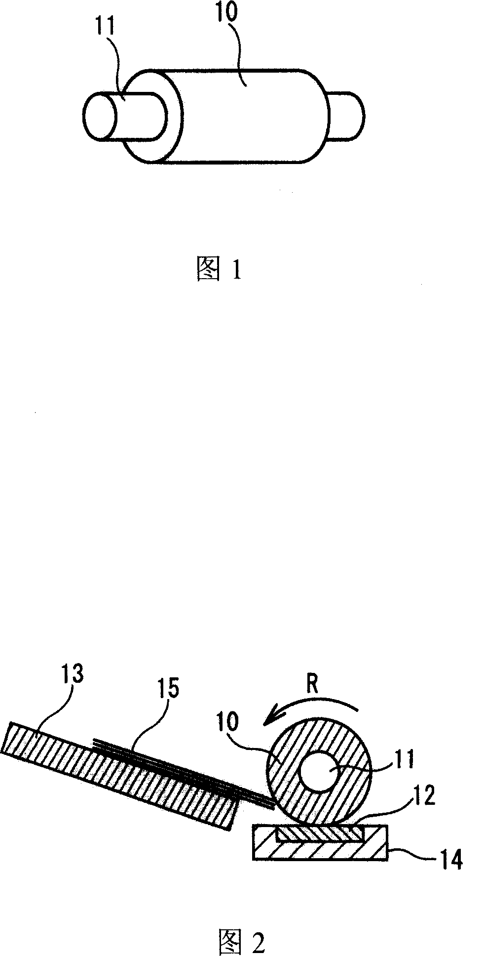
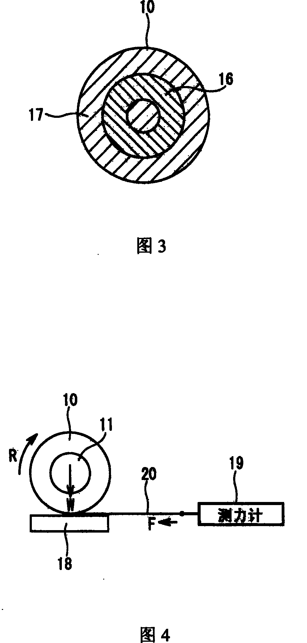
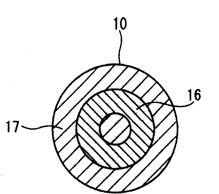
Paper feed roller
一种给纸辊、外层的技术,应用在给纸辊领域,能够解决渗出、没有考虑阻止橡胶组合物物质迁移等问题,达到长使用寿命、减少抖动现象、高耐磨性的效果
- Summary
- Abstract
- Description
- Claims
- Application Information
AI Technical Summary
Problems solved by technology
Method used
Image

Examples
Embodiment 1~5
[0088] Embodiment 1~5 and comparative example 2~3
[0089] (i) Forming the inner layer
[0090] Put the rubber composition specified in Table 2 into a prefabricated mold, and vulcanize under pressure at 160° C. for 30 minutes. Thus, a cylinder with an inner diameter of φ9mm, an outer diameter of φ15mm and a length of 60mm is obtained. Finally, the cylinder is cut into rubber rollers with a length of 10mm.
[0091] (ii) forming the outer layer
[0092] Put the rubber composition specified in Table 2 into a prefabricated mold, and vulcanize under pressure at 160° C. for 20 minutes. Thus, a cylinder with an inner diameter of φ14mm, an outer diameter of φ21mm and a length of 60mm is obtained. Next, the prepared cylinder was ground with a cylindrical grinder until the outer diameter became φ20 mm. Finally, the cylinder is cut into rubber rollers with a length of 10 mm.
[0093] (iii) Forming a paper feed roller with a double-layer structure
[0094] Insert the shaft into t...
PUM
| Property | Measurement | Unit |
|---|---|---|
| hardness | aaaaa | aaaaa |
| hardness | aaaaa | aaaaa |
| diameter | aaaaa | aaaaa |
Abstract
Description
Claims
Application Information
 - R&D Engineer
- R&D Manager
- IP Professional
- Industry Leading Data Capabilities
- Powerful AI technology
- Patent DNA Extraction
Browse by: Latest US Patents, China's latest patents, Technical Efficacy Thesaurus, Application Domain, Technology Topic, Popular Technical Reports.
© 2024 PatSnap. All rights reserved.Legal|Privacy policy|Modern Slavery Act Transparency Statement|Sitemap|About US| Contact US: help@patsnap.com