
Reciprocating guide mechanism for needle loom

A guiding mechanism and acupuncture machine technology, applied in the direction of acupuncture machine, engine lubrication, mechanical equipment, etc., can solve the problems of difficult assembly, complicated but not simple, acupuncture machine loses its price advantage, etc., and reduce lubricating oil. The probability of leakage, the effect of simple structure

Inactive Publication Date: 2007-05-23
常熟市伟成非织造成套设备有限公司
View PDF1 Cites 6 Cited by
  • Summary
  • Abstract
  • Description
  • Claims
  • Application Information

AI Technical Summary

Problems solved by technology

However, this structure is more suitable for high-speed needle looms, but not suitable for ordinary needle looms with low speed (about 600-700n / min).
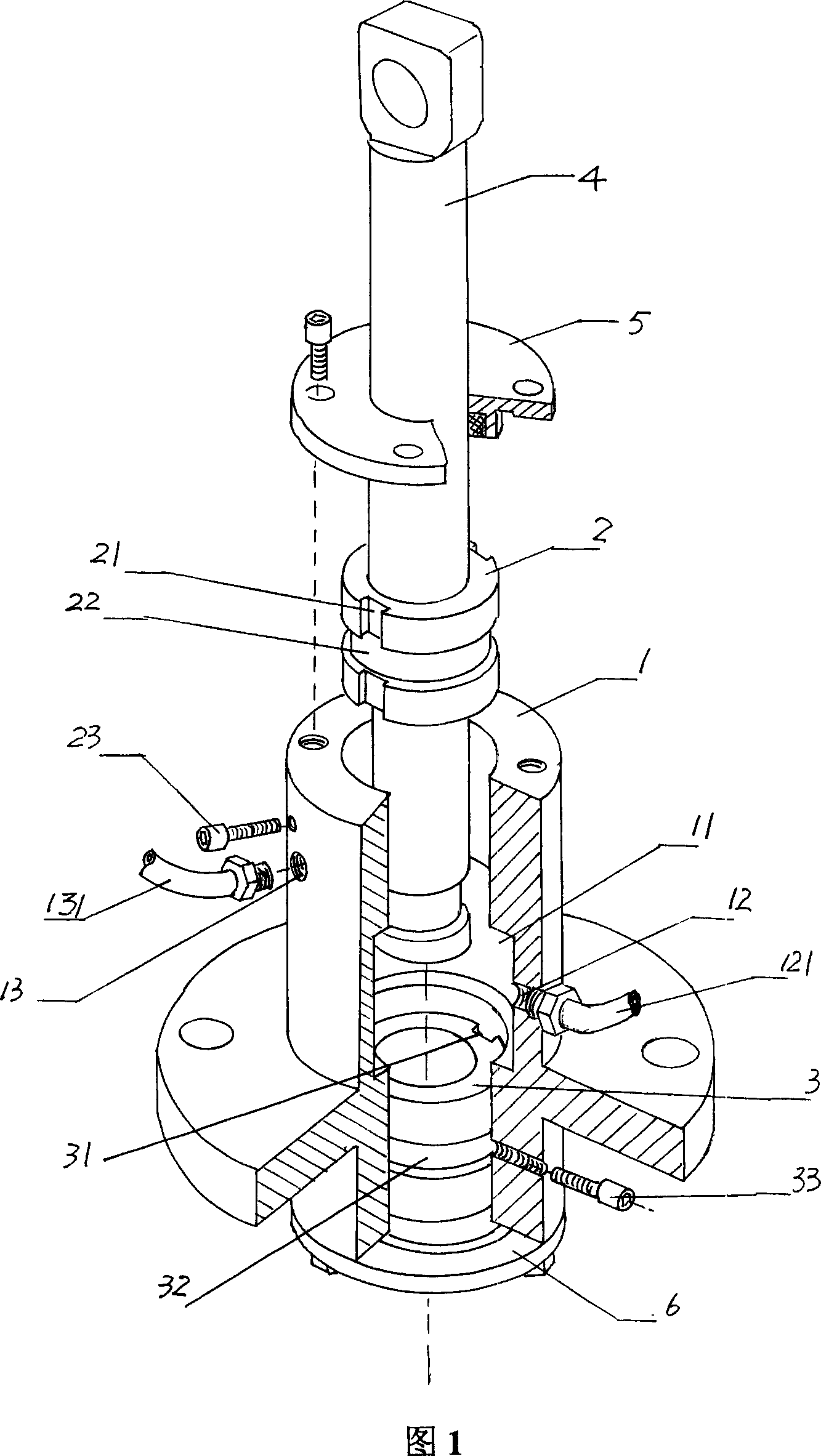
One is to equip an ordinary acupuncture machine with a set of complicated but not simple structures consisting of an oil tank, a coarse filter, a gear pump, a motor, a fine filter, etc. 2) The lubricating oil source device will cause configuration waste, and the processing and installation of the lubricating oil source device are also relatively troublesome; the second is to deliberately process the upper and lower guide sleeves 2 and 3, for example, the upper and lower Oil grooves 21, 31 and grooves 22, 32 are respectively provided on the guide sleeves 2, 3, so the process is very cumbersome. The upper and lower ends of the cavity of the sleeve seat 1, so the assembly is difficult and the requirements are strict; the third is that opening too many through holes on the side of the guide sleeve seat 1 will increase the probability of lubricating oil leakage, for example, in addition to the necessary In addition to the first and second through holes 12 and 13 that pass through the cavity, through holes for screwing in positioning screws 23 and 33 need to be opened; the fourth is that the entire set of ordinary acupuncture machines will lose their due price advantage

Method used


Image

  • Reciprocating guide mechanism for needle loom
  • Reciprocating guide mechanism for needle loom
  • Reciprocating guide mechanism for needle loom

Examples


Embodiment Construction

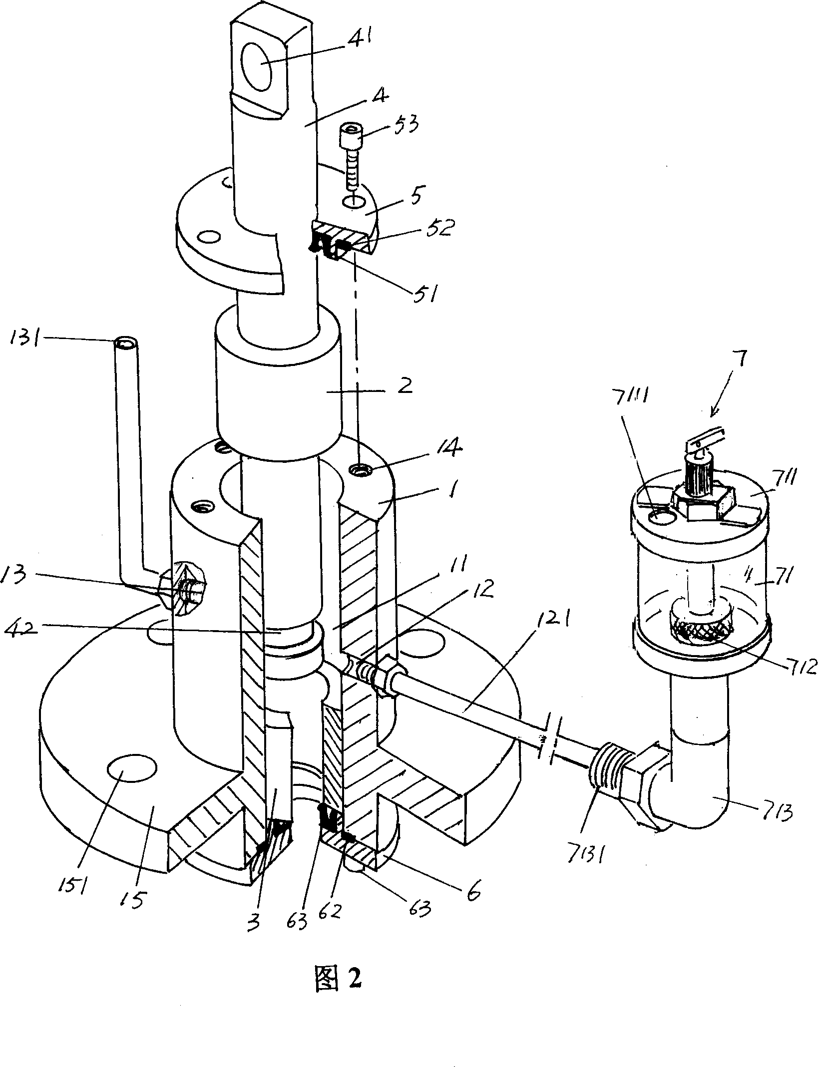
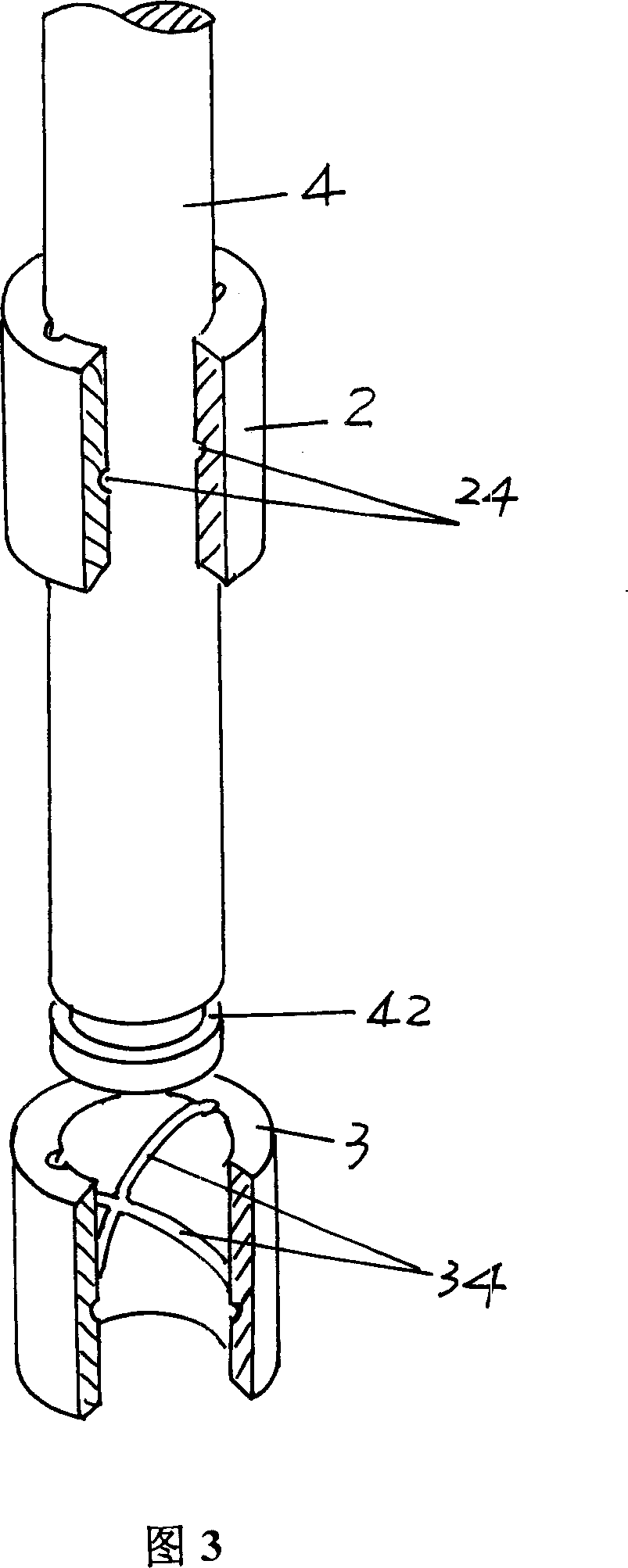
[0021] Please refer to Figure 2 and Figure 3, the longitudinal section of the guide sleeve 1 is in a convex shape, the upper end surface is provided with a screw hole 13, and the lower part is expanded into a mounting flange 15, and the upper part of the mounting flange 15 is provided with a mounting and fixing Hole 151. The cavity of the guide sleeve seat 1 is constituted as an oil chamber 11 , and the first and second through holes 12 and 13 are respectively opened on the side of the guide sleeve seat 1 and communicate with the oil chamber 11 respectively. As an embodiment, the oil storage container 7 shown in this figure as a lubricating oil source device is indirectly connected with the first through hole 12 through the oil inlet pipe 121 . Further, one end of the oil inlet pipe 121 (the left end shown in the figure) is threaded or welded with the first through hole 12, and the other end of the oil inlet pipe 121 (the right end shown in the picture) is threaded or welded w...


PUM


Abstract

It is about the reciprocating guiding mechanism of a needle machine. It comprises an oil cavity attached guide bushing base, upper and bottom guide bushings, propeller rod, upper and bottom sealing head, with No.1 and No.2 through holes connected with the oil cavity on both sides of the guide bushing base, the No.1 through hole connected with the lubricant source and the No.2 through hole with the tube channel. The upper and bottom guide bushings are located inside the upper and bottom end of the cavity of the guide bushing base with propeller rods inside them, the upper and bottom sealing head fastens to the upper and bottom end of the guide bushing base, featuring in the oil reservoir for lubricant sources, through fitting with the No.1 through hole. The said tube channel is used to as the exhaust for the air inside the oil cavity. It is simple in structure, simplifying the processing and installation of the upper and bottom sheath, reducing the possibility of leakage of lubricant, with natural lubricating effect.

Description

technical field [0001] The invention relates to a reciprocating guide mechanism of an acupuncture machine, which is used to realize a transitional transmission connection between the connecting rod of the acupuncture machine and the movable needle beam, so that the movable needle beam can reciprocate up and down, and belongs to the acupuncture machine field of application technology. Background technique [0002] As the reciprocating guide mechanism of the acupuncture machine, it is a mature technology on the acupuncture machine. It is composed of a guide sleeve seat, a pair of guide sleeves, a push rod, an upper and a lower sealing cover. The frame of the stab machine is fixed, a pair of guide sleeves (also known as copper sleeves) are respectively fixed on the upper and lower ends of the cavity of the guide sleeve seat, and the push rod is inserted into the pair of guide sleeves. The upper and lower ends are respectively connected with the connecting rod and the movable n...

Claims


Application Information

Patent Timeline
IPC IPC(8): D04H18/00F16N7/00D04H18/02
CPCD04H18/02
Inventor 王卫成
Owner 常熟市伟成非织造成套设备有限公司
Learn More