Movable garbage compression device

A garbage compression and mobile technology, applied in garbage storage, waste collection and transfer, transportation and packaging, etc., can solve the problems of sewage spilling, secondary pollution, etc., to avoid corrosion, improve service life, and avoid sewage leakage Effect

Active Publication Date: 2020-08-25
ZOOMLION ENVIRONMENTAL IND CO LTD
View PDF9 Cites 10 Cited by
  • Summary
  • Abstract
  • Description
  • Claims
  • Application Information

AI Technical Summary

Problems solved by technology

[0004] The invention provides a mobile garbage compression equipment to solve the technical problem that the existing mobile garbage compression equipment needs to contact the front-mounted garbage bucket for loading and transfer, which may easily cause sewage to spill and cause secondary pollution.

Method used


Image

  • Movable garbage compression device
  • Movable garbage compression device
  • Movable garbage compression device

Examples


Embodiment Construction

[0036] The embodiments of the present invention will be described in detail below with reference to the accompanying drawings, but the present invention can be implemented in many different ways defined and covered by the claims.

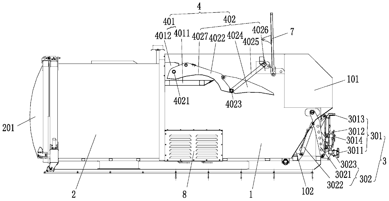
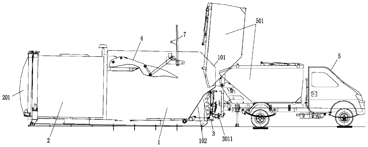
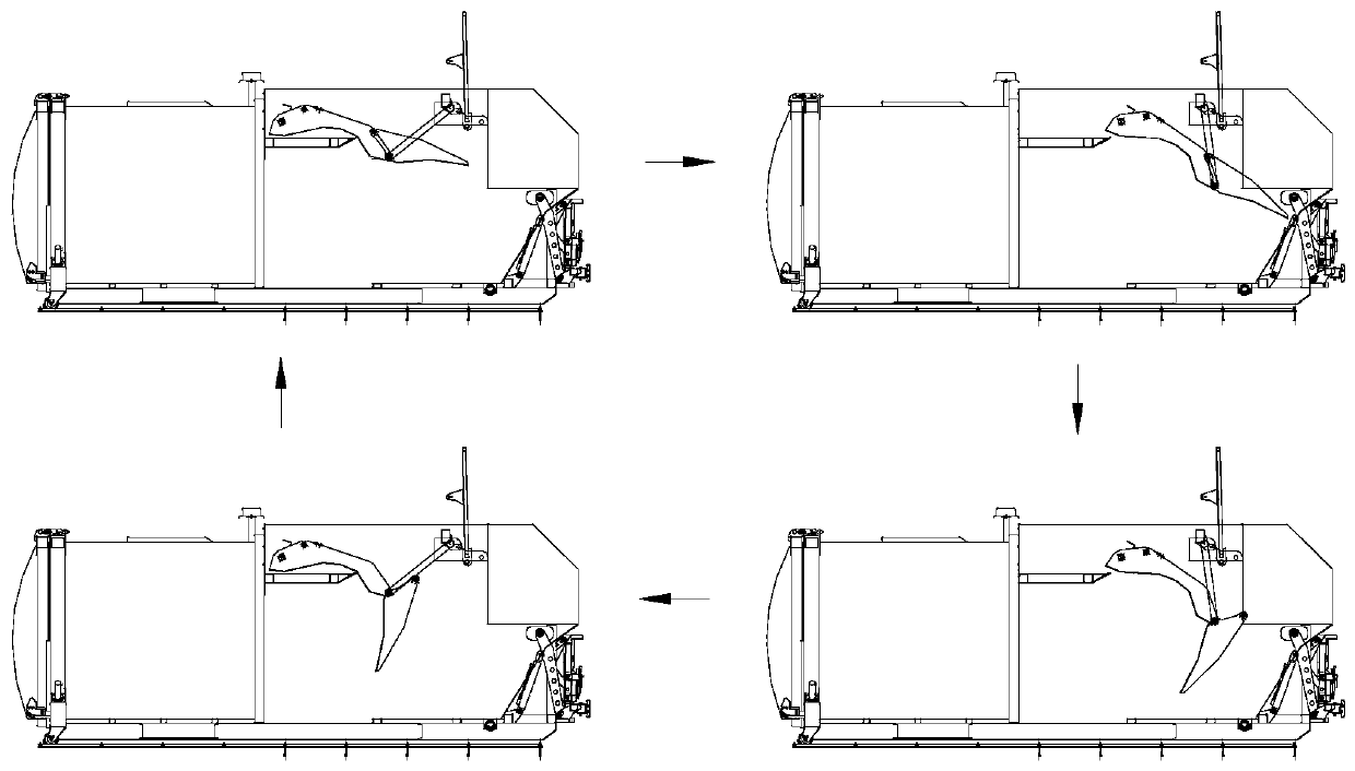
[0037] figure 1 It is a schematic structural diagram of a mobile garbage compression device in a preferred embodiment of the present invention; figure 2 It is a structural schematic diagram of the docking unloading vehicle and the mobile garbage compression equipment docking unloading in the preferred embodiment of the present invention; image 3 It is a structural schematic diagram of the compaction cycle of the mobile garbage compression equipment in the preferred embodiment of the present invention; Figure 4 It is a schematic diagram of the structure of the mobile garbage compacting equipment to prevent sewage spilling according to the preferred embodiment of the present invention; Figure 5 It is a structural schematic diagram of a bucket tu...


PUM


Abstract

The invention discloses a movable garbage compression device. The movable garbage compression device comprises a compression bin used for compressing garbage entering the equipment inwards and a garbage can connected with the output end of the compression bin and used for receiving the garbage output by the compression bin and storing the garbage, wherein a discharging opening used for dischargingthe garbage and a discharging door covering the discharging opening in a sealing manner are arranged at the end, away from the compression bin, of the garbage can; a feeding opening used for feedingthe garbage is formed in the end, away from the garbage can, of the compression bin; the height of the wall body of the feeding side of the feeding opening is matched with the discharging height of abutt joint discharging vehicle so that a discharging box of the butt joint discharging vehicle can be overturned into the feeding opening to conduct direct butt joint discharging; a can overturning mechanism used for hooking the garbage can and overturning the garbage can to the position of the feeding opening to dump the garbage is further arranged outside the wall body of the feeding side of thefeeding opening; the can overturning mechanism is further used for serving as anti-collision limiting of the butt joint discharging vehicle; and a pressing filling mechanism used for pushing and pressing the garbage entering the compression bin from the upper portion is arranged at the upper portion of an inner cavity of the compression bin.

Description

technical field [0001] The invention relates to the technical field of garbage transfer treatment equipment, in particular, to a mobile garbage compression equipment. Background technique [0002] The mobile garbage compression equipment integrates "airtightness, deodorization, compression, and storage" into one, realizing cleanliness, beauty, safety, efficiency, and environmental protection. Image and aesthetics can better enhance the overall image of the city. [0003] At present, the commonly used feeding form of mobile garbage compression equipment is the front-loading garbage hopper. It is necessary to pour the garbage into the front garbage hopper, and then turn up the garbage hopper to unload the garbage into the compression bin. Due to the high water content and strong fluidity of wet garbage, it is usually collected and transported in barrels. At the garbage transfer station, the garbage in the garbage can is dumped into the garbage hopper, and then the garbage hop...

Claims


Application Information

Patent Timeline
Patent Type & Authority Applications(China)
IPC IPC(8): B65F3/00B65F3/14B65F3/04B65F3/24
CPCB65F3/00B65F3/14B65F3/043B65F3/24B65F2003/006Y02W30/10
Inventor 郝长千戴强德谭清江李洪超申微尘
Owner ZOOMLION ENVIRONMENTAL IND CO LTD
Why Eureka
Try Eureka