Gas aspiration and compression system, especially for gas compressors

A gas compressor and compression system technology, applied in the field of gas compressors, can solve problems such as insufficient pistons, and achieve the effects of avoiding the reduction of the surface area, improving efficiency, and avoiding the reduction of volumetric performance

Inactive Publication Date: 2007-05-23
APPLIANCES COMPONENTS SPAIN
View PDF0 Cites 0 Cited by
  • Summary
  • Abstract
  • Description
  • Claims
  • Application Information

AI Technical Summary

Problems solved by technology

[0008] However, it has also been found in practice that in the case of small diameters, the disadvantage is that there is not enough space in the head of the piston to place all the valves (inlet and outlet)

Method used


Image

  • Gas aspiration and compression system, especially for gas compressors
  • Gas aspiration and compression system, especially for gas compressors
  • Gas aspiration and compression system, especially for gas compressors

Examples


Embodiment Construction

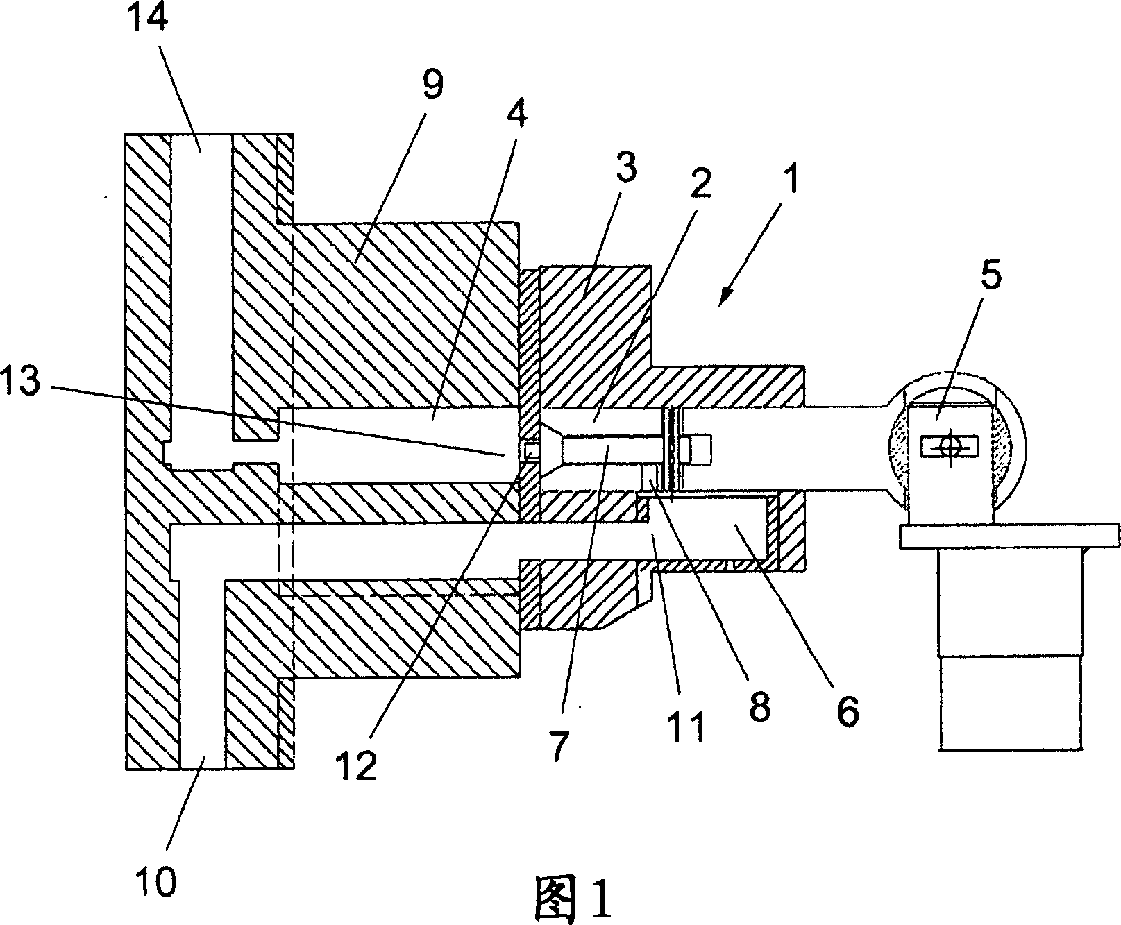
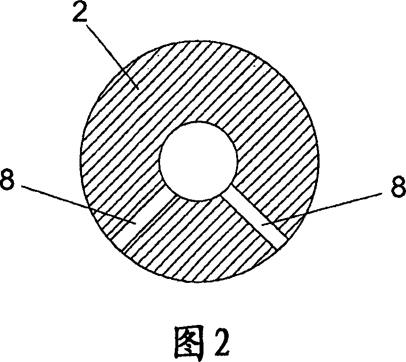
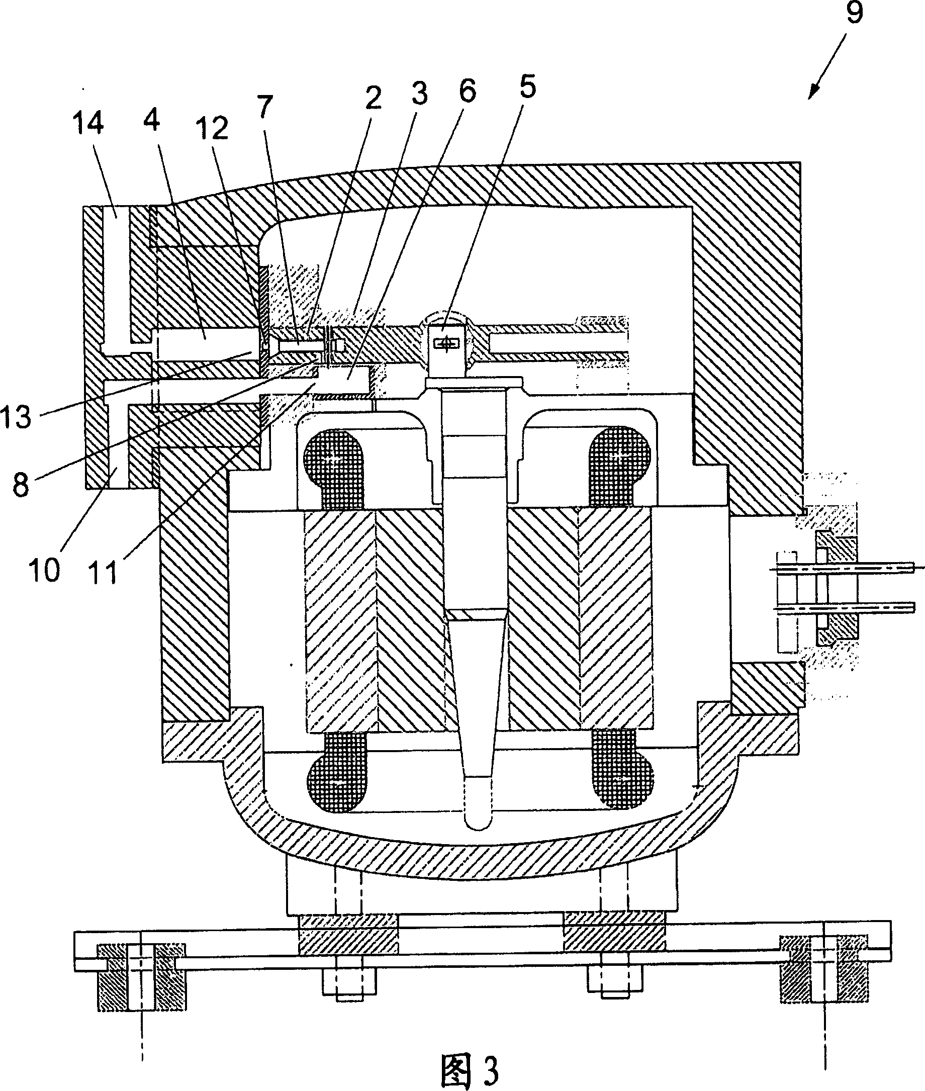
[0023] As shown in Figure 1, the gas suction and compression system 1 of the present invention comprises a piston 2 of very small diameter, preferably less than 11 mm, which cooperates with a cylinder 3 of a compression chamber 4, said piston 2 being in such a Connect to the scotch yoke mechanism 5 in the way. The system 1 of the present invention also includes a gas suction port 6 arranged on the side area of ​​the cylinder 3 near the bottom dead center of the piston 2, and a P-V optimization valve 7 (P-V is pressure-volume) arranged in the center of the piston 2 , are radially formed in the piston 2 and connect the suction port 6 and the two orifices 8 of the P-V optimization valve 7 . The orifice 8 of the piston 2 can thus move along the suction opening 6 so that gas enters the compression chamber 4 during the suction stroke of the piston 2 and prevents the gas from passing through during the compression stroke of the piston 2 . With this design, there is no need to use a ...


PUM


Abstract

Gas aspiration and compression system, especially for gas compressors. It includes a piston (2) of markedly small diameter associated with a cylinder (3) of a compression chamber (4). It is characterised in that it includes a gas intake port (6) at a lateral zone of the cylinder (3) near the bottom dead centre point of the piston (2), a P-V optimisation valve (7) mounted inside the piston (2), and at least one hole (8) made inside the piston (2) in a radial direction that connects said intake port (6) with the P-V optimisation valve (7), in such a way that the at least one hole (8) is moveable along the intake port (6), permitting entry of the gas towards the compression chamber (4) during the piston intake stroke (2) and closure of the gas during the piston compression stroke (2). Increased energy efficiency of the compressor is achieved and the intake valve in the piston head is eliminated.

Description

technical field [0001] The present invention relates to a gas suction and compression system, especially suitable for gas compressors. Background technique [0002] As we all know, the current new challenge is environmental protection, especially the mandatory reduction of greenhouse gas emissions in accordance with the Kyoto Protocol on climate change. What industrialized countries are facing is that the refrigeration industry needs to find the current high GWP (Global Global Warming Potential) HFC (hydrofluorocarbons, hydrofluorocarbons) type refrigerant replacement. [0003] In this paper, carbon dioxide itself exists as a compound with a good chance of being accepted as a refrigerant by vapor compression in the refrigeration cycle. Important properties of carbon dioxide are its high working pressure, high discharge temperature and high volumetric capacity. These features mean that a two-stage compression process with intercooling is highly desirable in low-pressure suc...

Claims


Application Information

Patent Timeline
Patent Type & Authority Applications(China)
IPC IPC(8): F04B39/12F04B39/10F04B39/00F04B35/04
CPCF04B7/04F04B39/0016F04B39/122F04B27/0878F04B53/12
Inventor 何塞·萨罗·阿隆索
Owner APPLIANCES COMPONENTS SPAIN
Why Eureka
Try Eureka