Electric heat exchanger and ventilation system using same

A technology of an exchanger and a heat exchange element, which is applied in the field of ventilation systems, can solve the problems such as the reduction of the electric heat efficiency of the electric heat exchanger, the lower efficiency of the electric heat exchanger, and the inability to effectively perform heat exchange operations.

Inactive Publication Date: 2007-05-23
LG ELECTRONICS (TIANJIN) APPLIANCES CO LTD
View PDF0 Cites 4 Cited by
  • Summary
  • Abstract
  • Description
  • Claims
  • Application Information

AI Technical Summary

Problems solved by technology

[0018] First, when designing the building, due to the limitation of the height of the ceiling, the height of the electric heat exchanger will be limited, and thus the height of the heat exchange element will also be limited. As a result, the height of the heat exchange element is limited The size of the heat exchange area will be limited, resulting in a relative reduction in the electrothermal efficiency of the electric heat exchanger
[0019] Second, because the flow rate of air passing through the heat exchange element is too high, the heat exchange operation will not be effective in the above heat exchange element, and the efficiency of the electric heat exchanger will become low
[0020] Third, due to the large bend in the flow direction of the suction flow path and the exhaust flow path, the pressure loss through the flow path is large

Method used


Image

  • Electric heat exchanger and ventilation system using same
  • Electric heat exchanger and ventilation system using same
  • Electric heat exchanger and ventilation system using same

Examples


Embodiment Construction

[0058] Next, the first embodiment of the electric heat exchanger in the present invention will be described with reference to accompanying drawings 2 to 4b.

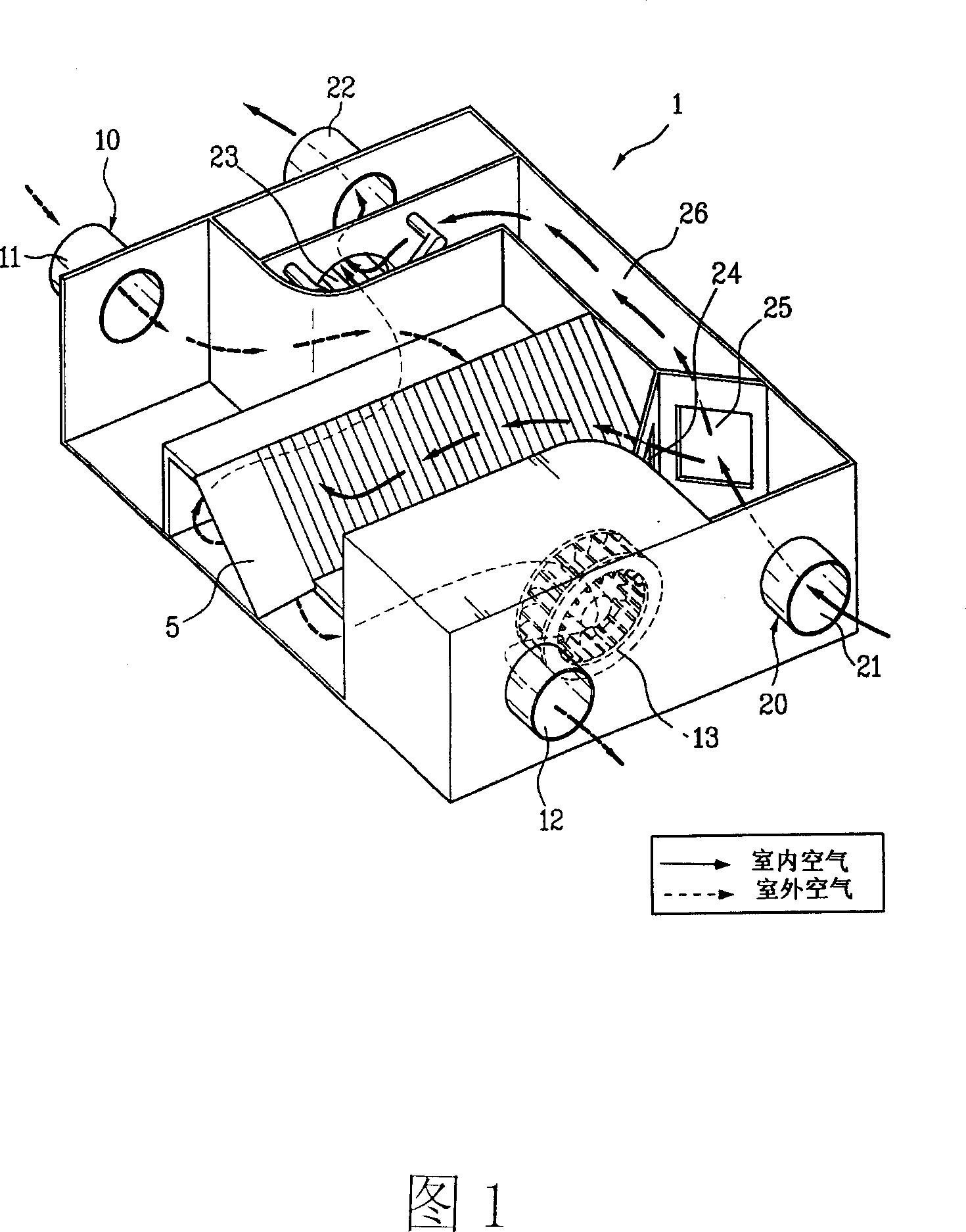
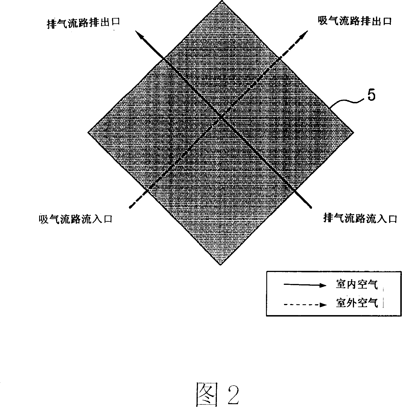
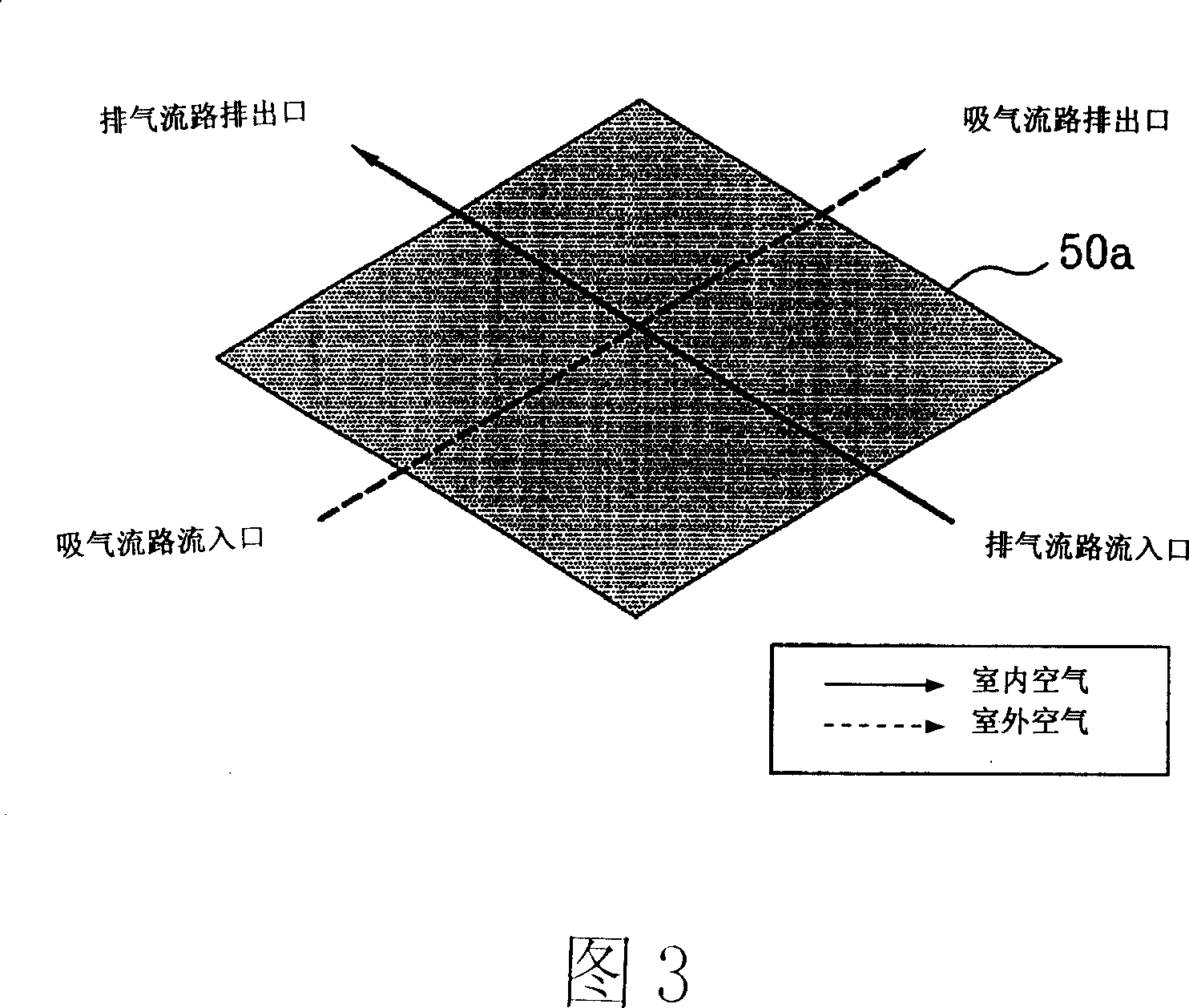
[0059] As shown in Fig. 2 and Fig. 3, the basic structure of the first embodiment of the electric heat exchanger in the present invention is the same as that of the conventional electric heat exchanger shown in Fig. 1 . That is, it includes: a heat exchange element 50a, which makes outdoor air and indoor air perform heat exchange; a suction fan 13, which is connected to the above-mentioned suction flow path 10, sucks the above-mentioned outdoor air, and discharges it into the room; The air fan 23 is connected to the above-mentioned exhaust flow path 20, sucks the above-mentioned indoor air, and discharges it to the outside. However, the cross-sectional shape of the heat exchange element 50a is different from that of the prior art, and is formed in a polygonal shape whose length in the horizontal or vertical direction is ...


PUM


Abstract

A heat and electricity exchanger comprises heat exchanging components installed at the cross section of the exhaust channel and the absorbing channel, allowing the exchange of heat of the indoor and outdoor air, air absorbing fan absorbs air inside room, exhaust fan expels indoor air out, with the cross section of the heat exchanging unit forming into a multi angle shape with the horizontal or vertical length longer than lengths in other directions, with the cross section of the heat exchanging component in four angular shape. Though lowering down the air flow inside the heat exchanging component, reducing the curve degree of the air absorption and exhaust flow channel, it can reduce the pressure loss going through the flow channel.

Description

technical field [0001] The invention relates to an electric heat exchanger and a ventilation system using the electric heat exchanger. Background technique [0002] When a user who is active indoors is breathing or the like, the air in the closed room is gradually polluted over time. Therefore, it is necessary to replace indoor polluted air with outdoor fresh air at any time. For this purpose, an electric heat exchanger and a ventilation system using an electric heat exchanger are generally used. Here, the electric heat exchanger is a device that supplies outside air and discharges indoor air while maintaining the temperature of indoor air. [0003] As shown in Figure 1, the existing electric heat exchanger includes: a heat exchange element 5, which is installed in the suction flow path 10 as the passage for supplying outdoor air to the room, and the exhaust flow path 10 as the passage for the indoor air to be discharged to the outside. On the area where the air flow path ...

Claims


Application Information

Patent Timeline
Patent Type & Authority Applications(China)
IPC IPC(8): F24F12/00
Inventor 金暻桓崔瑾荧崔东焕
Owner LG ELECTRONICS (TIANJIN) APPLIANCES CO LTD
Why Eureka
Try Eureka