
Petroleum heating device

A heating device, oil technology, applied in the pipeline system, mechanical equipment, gas/liquid distribution and storage, etc., can solve the problems of large temperature gradient, slow heat transfer, large maintenance, etc., and achieve uniform distribution of temperature field and easy control The effect of high temperature and electric heating efficiency

Inactive Publication Date: 2008-12-03
CHINA UNIV OF PETROLEUM (BEIJING)
View PDF5 Cites 0 Cited by
  • Summary
  • Abstract
  • Description
  • Claims
  • Application Information

AI Technical Summary

Problems solved by technology

The three-pipe hot water mixing heat transmission device and the two-pipe steam mixing heat transmission device heat the heavy oil transported in one heating pipe through two hot water mixing pipes and steam pipes respectively, and pass through many designed on the conveying route. Heating stations use boilers to provide hot water or steam to heat oil in pipelines, so there are defects in energy and steel consumption, serious environmental pollution, and a large amount of human resources
Compared with the three-pipe hot water mixing heat transmission method, the two-pipe steam mixing heat transmission method and the electric heating belt transmission method, the skin effect electric heat tracing transmission method and the power frequency heating transmission method have certain advantages, but they also use the pipeline As a medium, the oil in the pipeline is indirectly heat-exchanged from the outside through the pipeline, so there are the following disadvantages: the temperature gradient between the oil to be heated and the heat source is large, the heat transfer is slow, and it is not conducive to controlling and adjusting the temperature of the oil; A large number of insulation materials avoid excessive heat loss, so the cost is high; the maintenance required is large; heat loss is serious, wasting energy

Method used


Image

  • Petroleum heating device
  • Petroleum heating device
  • Petroleum heating device

Examples


Embodiment Construction

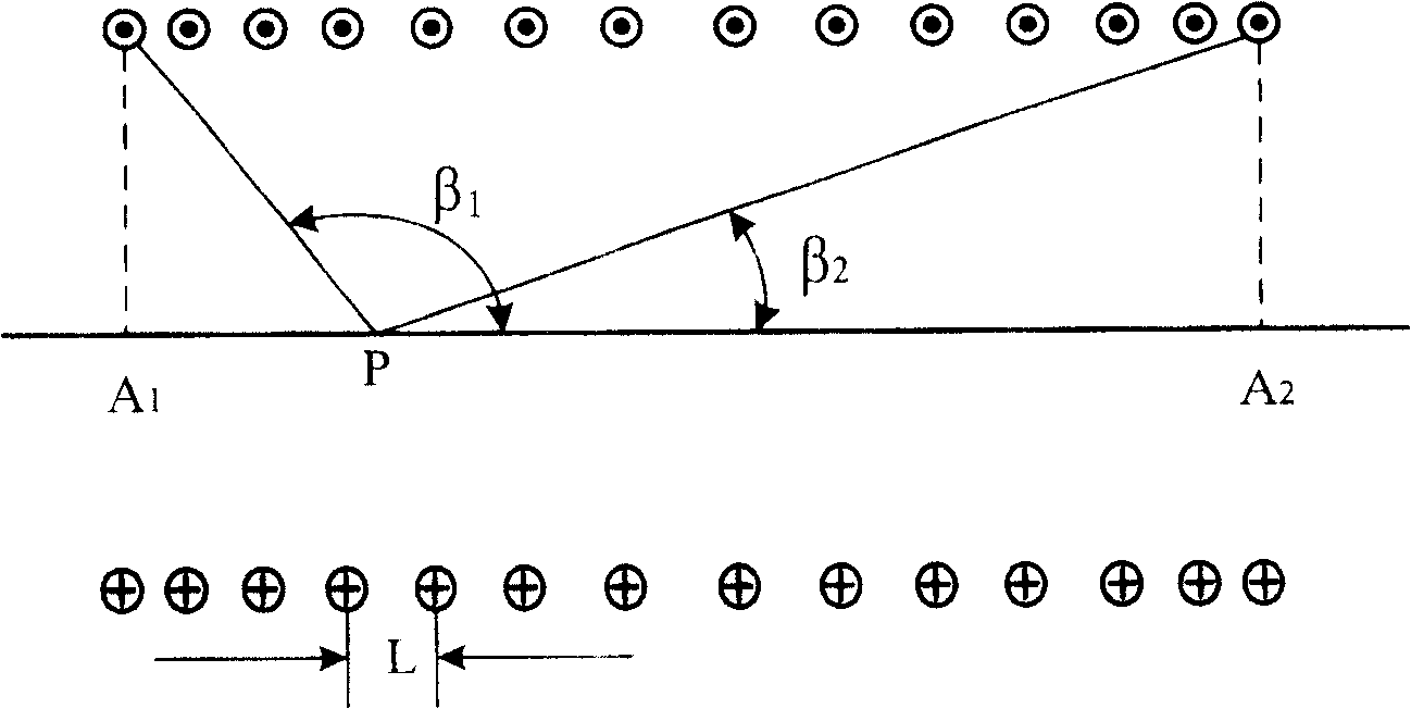
[0020] The present invention adopts the principle of electromagnetic induction heating to heat the oil transported in the heating pipeline from the inside, and the heating principle is as follows: after the alternating current is passed into the helical tubular induction coil, an alternating magnetic field will be generated in the coil, and the magnetic field The magnetic induction intensity is:

[0021] B = μ 2 nI ( cos β 1 - cos β 2 ) - - - ( 1 )

[0022] In the above formula (1), B is the magnetic induction at a certain point P inside the induction coil, μ is the magnetic permeability of the magnetic medium inside the induction ...


PUM


Abstract

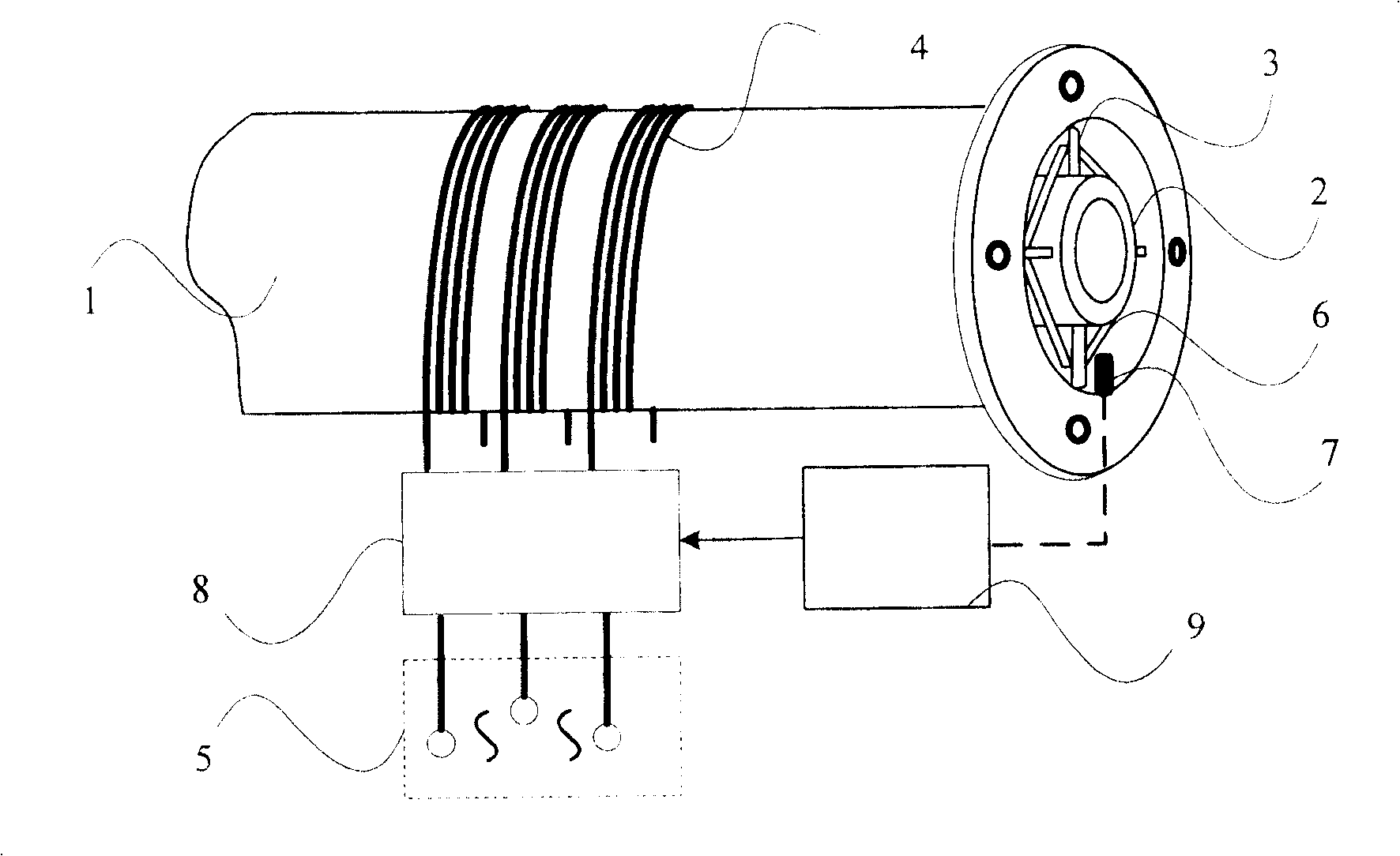
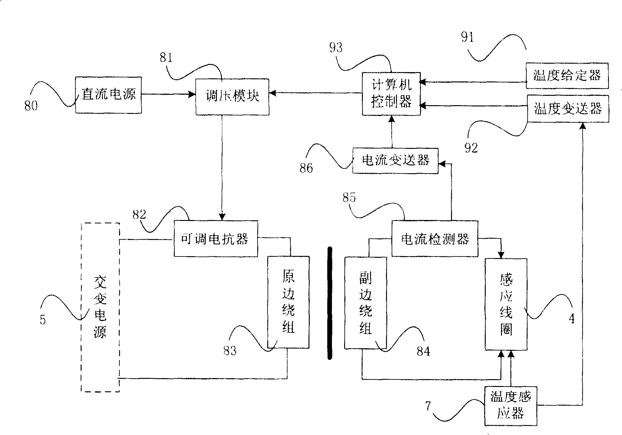
The invention relates to an oil heating device, which comprises a heating tube made form non-metallic material. Wherein, the heating tube via the support elements comprises the heating elements made form metals to heat the oil; the outer surface of said heating tube is coiled with the sensing coil connecting the alternating current power. The invention uses the electromagnetic sensing theory to heat transmitted oil inside the oil tube, with high electric heating efficiency and reduce the heat loss, without using thermal-insulating material to avoid the heat loss between the heated oil and the heat source. It has less maintenance and lower cost. The oil in the heating tube can be heated when flowing along the inner and outer surfaces of heating elements, while the temperature field inside the oil is uniform distributed to make the temperature control easily. The invention makes the heating elements emit heat according to the electromagnetic sensing theory and uses the heating elements to heat oil without environment pollution.

Description

technical field [0001] The invention relates to a petroleum heating device, in particular to a petroleum heating device which is installed in a petroleum transportation pipeline and heats the petroleum conveyed in the pipeline. Background technique [0002] Since the melting point of petroleum is higher than normal temperature, it is viscous at normal temperature or in low temperature areas. Therefore, it is very difficult to directly transport the mined oil for long distances through pipelines in normal temperature or low temperature areas. To overcome this Difficult, it is usually necessary to heat the oil flowing through the pipeline in order to reduce its viscosity and make it fluid. [0003] In the prior art, a three-pipe hot water mixing heat transmission device, a two-pipe steam mixing heat transmission device and an electric heat tracing transmission device are usually used to heat the transported oil. The three-pipe hot water mixing heat transmission device and the...

Claims


Application Information

Patent Timeline
Patent Type & Authority Patents(China)
IPC IPC(8): F17D1/18
Inventor 梁志珊
Owner CHINA UNIV OF PETROLEUM (BEIJING)
Learn More