
LCD device

A liquid crystal display and liquid crystal display panel technology, applied in the direction of instruments, nonlinear optics, optics, etc., can solve the problems of uneven light brightness of liquid crystal display, and achieve the effect of reducing the number of point light sources, reducing manufacturing costs, and uniform light brightness

Inactive Publication Date: 2007-05-23
INNOCOM TECH SHENZHEN +1
View PDF0 Cites 0 Cited by
  • Summary
  • Abstract
  • Description
  • Claims
  • Application Information

AI Technical Summary

Problems solved by technology

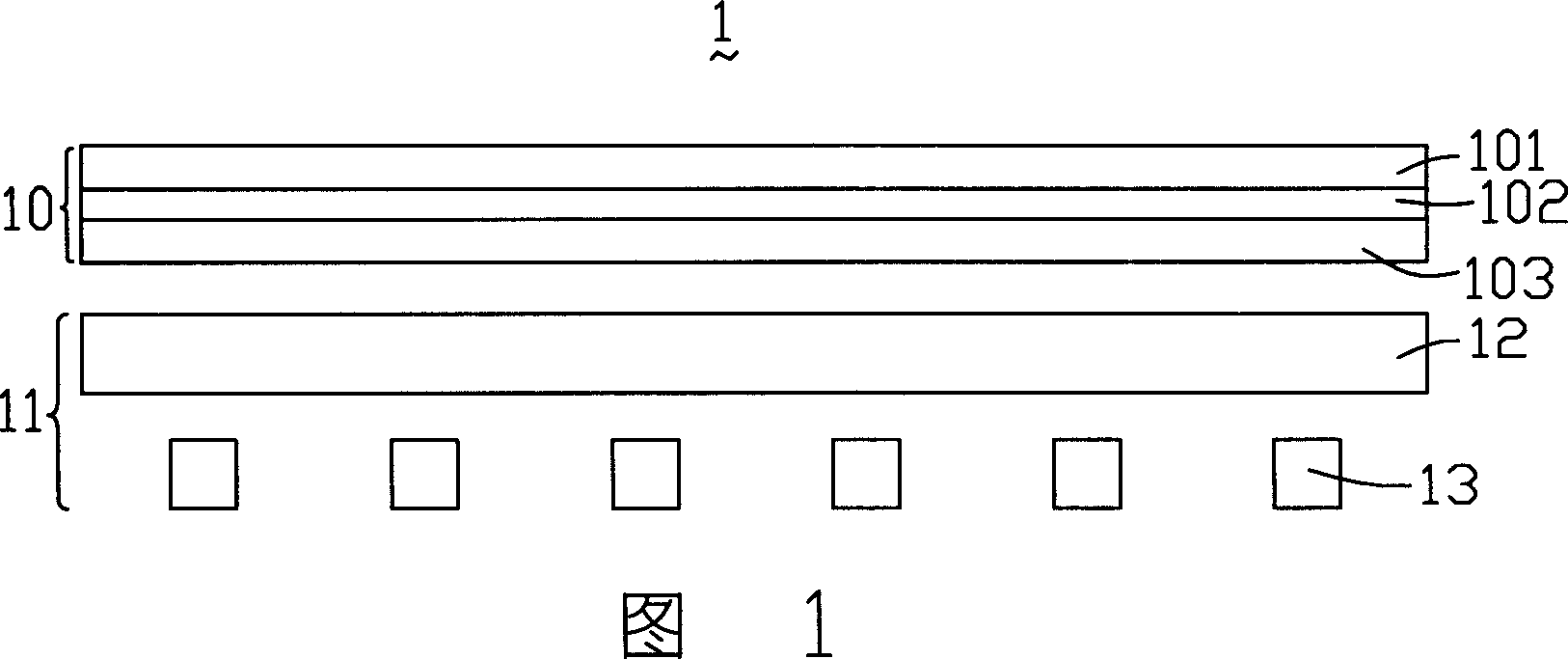
[0006] In order to solve the problem of uneven light emitting brightness of liquid crystal displays in the prior art, it is necessary to provide a liquid crystal display with relatively uniform light emitting brightness

Method used


Image

  • LCD device
  • LCD device
  • LCD device

Examples


Embodiment Construction

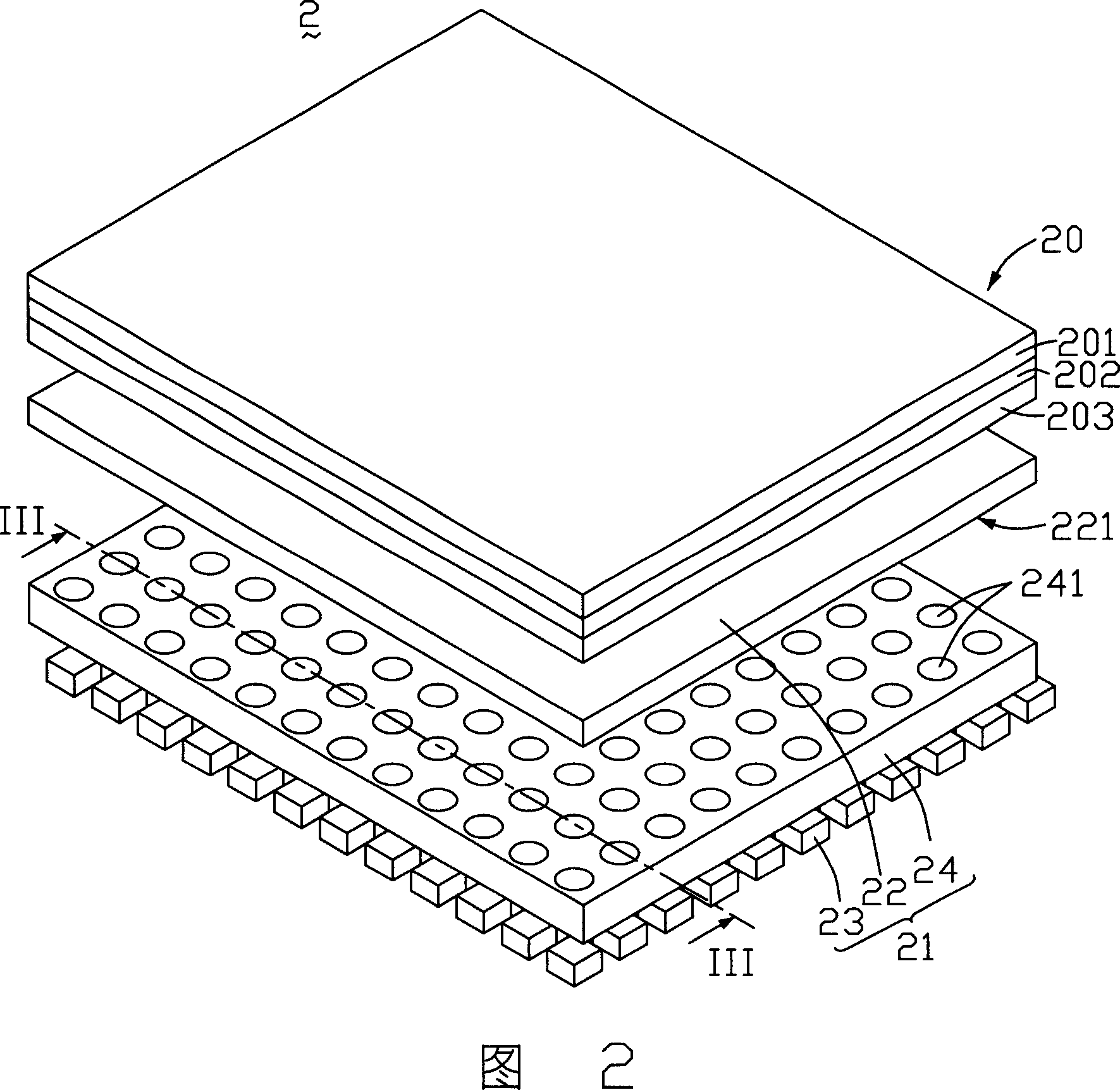
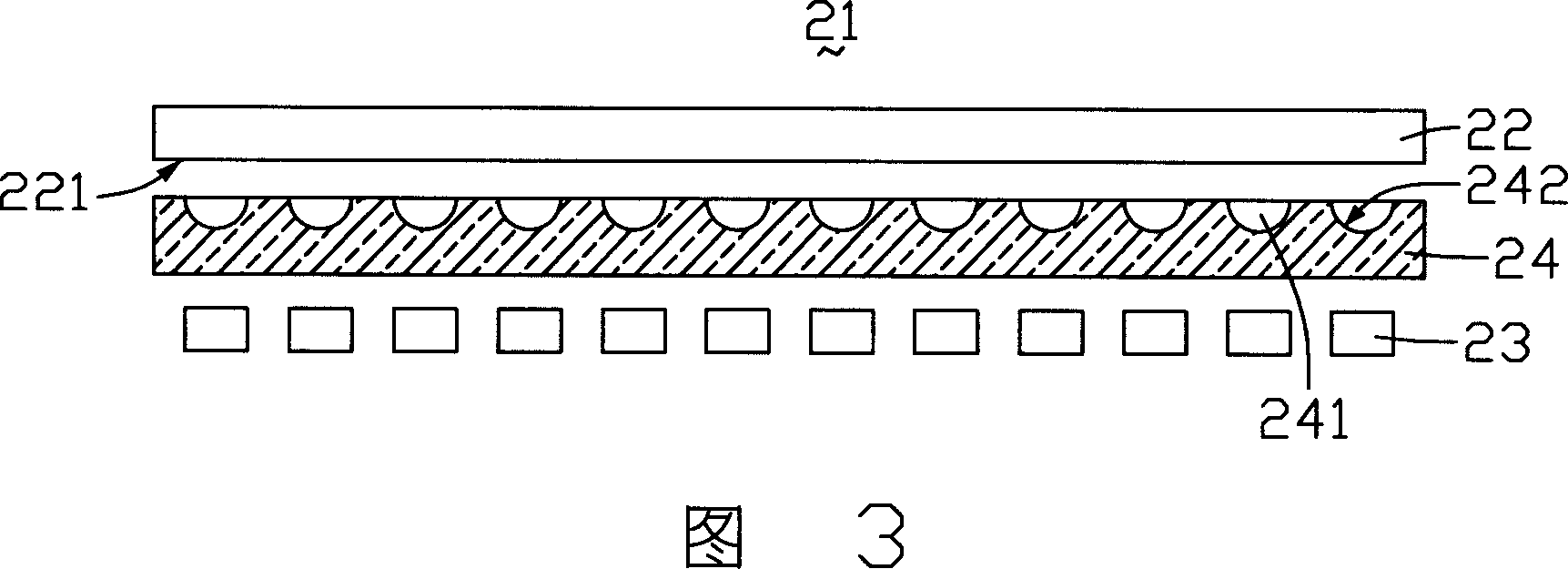
[0019] Please refer to FIG. 2 and FIG. 3 , FIG. 2 is an exploded perspective view of the first embodiment of the liquid crystal display of the present invention, and FIG. 3 is a sectional view along III-III in FIG. 2 . The liquid crystal display 2 includes a liquid crystal display panel 20 and a backlight module 21 . The backlight module 21 provides planar light for the liquid crystal display panel 20 .

[0020] The liquid crystal display panel 20 includes a first substrate 201 , a liquid crystal layer 202 and a second substrate 203 , the two substrates 201 , 203 are opposite to each other, and the liquid crystal layer 202 is sandwiched between the two substrates 201 , 203 .

[0021] The backlight module 21 includes a light guide plate 22 with a light incident surface 221, a plurality of point light sources 23 arranged on the side of the light incident surface 221 below the light guide plate 22, and a light emitting area arranged between the plurality of point light sources 23...


PUM


Abstract

The invention discloses a LCD display, including an LCD panel and a backlight module. The backlight module is used for the lights of the LCD panel. The backlight module includes a illuminator with a smooth entry, an illumination installed at the entry point to the smooth side and a light installed at the point light source with the luminous zone between the Illuminator-regulation enclosures the cover-regulation in relation to the side of the illumination at least one cavity formation. The LCD light output is of high brightness uniformity.

Description

【Technical field】 [0001] The invention relates to a liquid crystal display. 【Background technique】 [0002] Due to the advantages of thinness, lightness, low power consumption, and no radiation, liquid crystal displays are widely used in electronic equipment such as notebook computers, mobile phones, digital cameras, and instrumentation for display terminals. However, since the liquid crystal layer itself cannot emit light, in order to achieve the display effect, a backlight module structure is usually used to provide the required light source. At present, in large-size liquid crystal displays, most of the light sources use cold cathode ray tubes, but because cold cathode ray tubes contain mercury (Hg), a substance harmful to human body, which does not meet the environmental protection requirements of products, it has been used by most The state expressly prohibits its use. [0003] At present, in large-size liquid crystal displays, the backlight module often adopts a dire...

Claims


Application Information

Patent Timeline
Patent Type & Authority Applications(China)
IPC IPC(8): G02F1/1335
Inventor 林精皇艾兵
Owner INNOCOM TECH SHENZHEN
Learn More