
LBD lamp assembly

A technology of light-emitting diodes and diodes, which is applied to electrical components, electric solid devices, circuits, etc., can solve problems such as inaccurate alignment, achieve the effects of reducing time, reducing production costs, and prolonging service life

Inactive Publication Date: 2007-05-23
LUSTROUS TECH
View PDF0 Cites 6 Cited by
  • Summary
  • Abstract
  • Description
  • Claims
  • Application Information

AI Technical Summary

Problems solved by technology

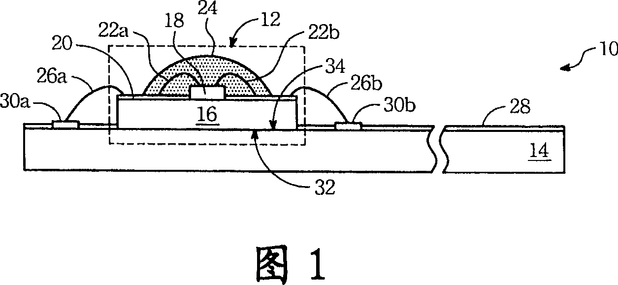
How to avoid the problem of inaccurate alignment in the process of connecting multiple LED packaging units 12 to the circuit board 14, and how to effectively release the heat generated by the LED packaging units 12 and the circuit board 14 to prolong the service life , is the primary goal of the present invention

Method used


Image

  • LBD lamp assembly
  • LBD lamp assembly
  • LBD lamp assembly

Examples


Embodiment Construction

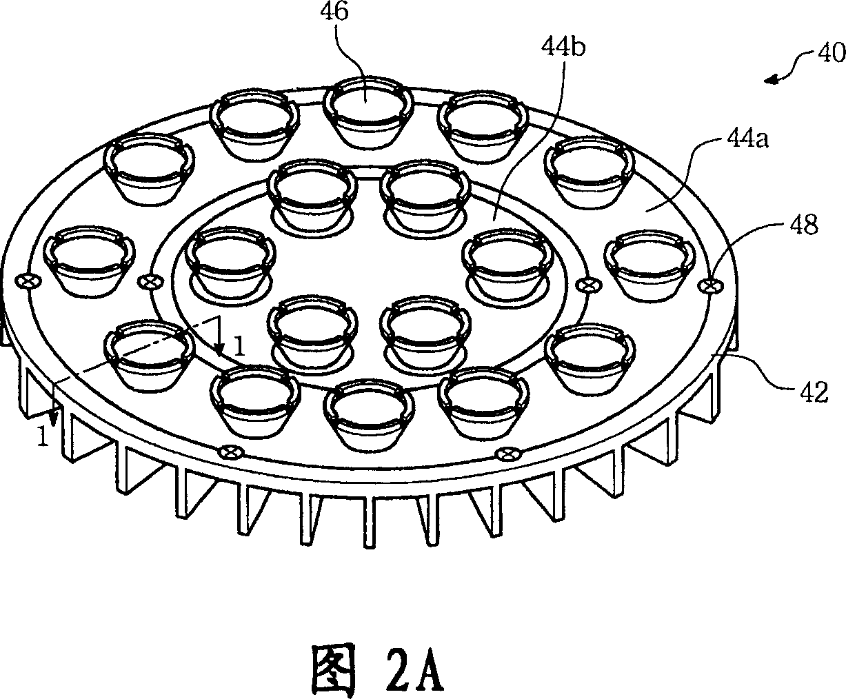
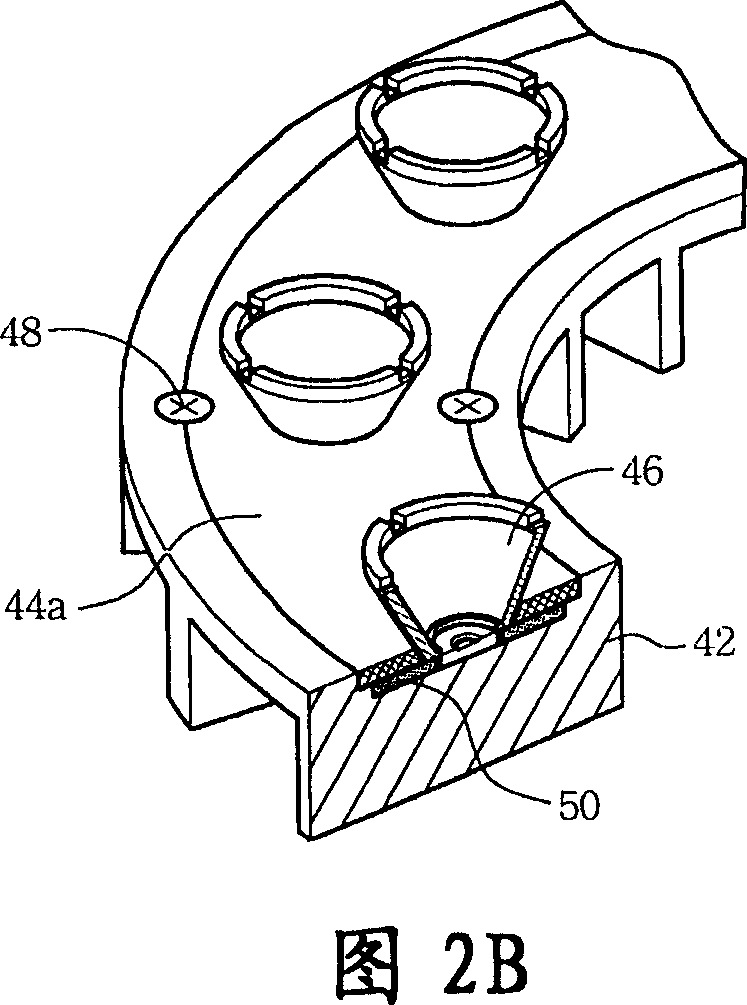
[0035] See Figure 2A. Fig. 2A is a schematic diagram of the LED lamp set of the present invention. The LED light set 40 provided by the present invention includes a base 42 , circuit boards 44 a and 44 b and a plurality of optical lenses 46 . In this embodiment, as shown in FIG. 2A , there are eighteen optical lenses 46 . Of course, the number and presence or absence of optical lenses are not limitations of the present invention.

[0036] The function of the base 42 is not only to accommodate internal components, but also to dissipate heat generated by the LED lamp set 40 during operation. The material of the base 42 can be selected from aluminum, copper, ceramic substrate, heat pipe or flat heat pipe (vapor chamber), so as to facilitate heat removal. Structurally, the base 42 can be designed to have a plurality of heat dissipation fins on its lower surface, also to enhance the heat dissipation effect.

[0037] The circuit boards 44 a and 44 b have a circuit board wire patt...


PUM


Abstract

The invention relates to a light emitting diode, which comprises light emitting diode packing unit and one circuit board, wherein said packing unit has one base board and one light emitting diode, and at least two packing unit electrodes on the upper face of base board and connected to the diode; said circuit board has one through hole through the upper and lower faces of circuit board; the upper face of base board is mounted on low face of circuit board; the through hole exposes said diode. The invention has better radiation, low mounting time, long service life and low cost.

Description

technical field [0001] The invention relates to a light-emitting diode illuminating lamp group. In particular, it relates to a light-emitting diode lamp group with the function of benefiting heat dissipation. Background technique [0002] Light Emitting Diode (LED, Light Emitting Diode) is becoming more and more popular in various electronic products and industries. Because the energy cost required is much lower than that of traditional incandescent or fluorescent lamps, and the size of a single light emitting diode is very light, it is Traditional light sources are beyond the reach. Therefore, under the trend of electronic products becoming thinner, lighter and smaller, the demand for light-emitting diodes is also increasing day by day. [0003] Please refer to FIG. 1 , which is a schematic diagram of a known LED lamp group. The LED lamp set 10 mainly includes one or more LED packaging units 12 and a circuit board 14 , and this figure only takes a single LED packaging uni...

Claims


Application Information

Patent Timeline
Patent Type & Authority Applications(China)
IPC IPC(8): H01L33/00H01L25/13H01L23/36H01L33/48H01L33/64
CPCH01L2224/48091H01L2924/181H01L2924/19107
Inventor 刘家齐季宝琪
Owner LUSTROUS TECH
Learn More