Dehumidification apparatus
A technology for wet end and hygroscopic agent, applied in heating methods, lighting and heating equipment, applications, etc., can solve the problems of complex device structure and high price
- Summary
- Abstract
- Description
- Claims
- Application Information
AI Technical Summary
Problems solved by technology
Method used
Image

Examples
Embodiment approach 1
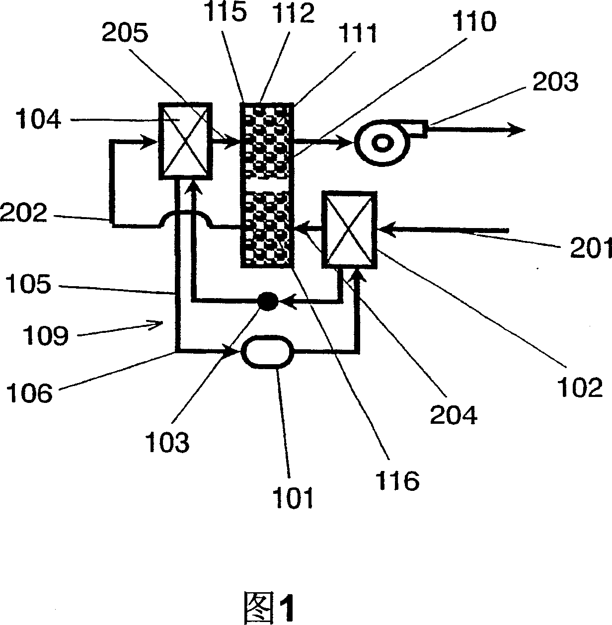
[0028] FIG. 1 is a schematic configuration diagram of a dehumidifier according to Embodiment 1 of the present invention. This dehumidifier has a heat pump 109 and a dehumidifier 110 . The heat pump 109 has a heat absorber 104 that absorbs heat from the supplied air, and a radiator 102 that dissipates heat into the supplied air. The moisture absorber 110 absorbs moisture from air with relatively high humidity, and then releases moisture into air with relatively low humidity. The moisture absorber 110 has a moisture absorption part 115 which absorbs moisture from the supplied air, and a moisture release part 116 which releases moisture into the supplied air. The supply duct (hereinafter referred to as duct) 202 supplies the air to be dehumidified to the radiator 102, the moisture release unit 116, the heat absorber 104, and the moisture absorption unit 115 in this order. That is, the radiator 102 heats the air to be dehumidified, and the dehumidification unit 116 humidifies th...
Embodiment approach 2
[0062] Fig. 6 is a schematic configuration diagram of a dehumidifier according to Embodiment 2 of the present invention. The dehumidifier in this embodiment includes a heat exchange unit 206 for exchanging heat between the dehumidification target air absorbed by the moisture absorption unit 115 and the dehumidification target air supplied to the radiator 102 . Other structures are the same as those in Embodiment 1.
[0063] The heat exchange unit 206 can be any part as long as it can exchange a certain amount of sensible heat of the air, and a cross-flow type, a counter-flow type laminated heat exchanger, and a radiation type heat exchanger that performs heat exchange by rotating a heat storage material can be used. . Next, the operation of the dehumidifier will be described.
[0064] Fig. 7 is a humid air diagram showing state changes of dehumidification target air in the dehumidifier shown in Fig. 6 . The air in the state of point 55 that has been absorbed by moisture in ...
Embodiment approach 3
[0069] Fig. 8 is a schematic configuration diagram of a dehumidifier according to Embodiment 3 of the present invention. The dehumidifier in the present embodiment includes cooling unit 207 that is humidified in dehumidification unit 116 and cools the air to be dehumidified supplied to heat absorber 104 . Other than that, the other structures are the same as those of Embodiment 1.
[0070] In the configuration of FIG. 8 , cooling unit 207 is constituted by a heat exchanger that exchanges heat between air humidified in dehumidifying unit 116 and supplied to heat absorber 104 and air supplied to radiator 102 . As long as the heat exchanger is capable of exchanging heat with a certain amount of sensible heat of the air, a cross-flow type, a counter-flow type laminated heat exchanger, and a radial-flow type that performs heat exchange by rotating a heat storage material can be used. heat exchanger.
[0071] In addition, the cooling part 207 is not limited to a heat exchanger, Wh...
PUM
| Property | Measurement | Unit |
|---|---|---|
| Average pore diameter | aaaaa | aaaaa |
Abstract
Description
Claims
Application Information
 - R&D Engineer
- R&D Manager
- IP Professional
- Industry Leading Data Capabilities
- Powerful AI technology
- Patent DNA Extraction
Browse by: Latest US Patents, China's latest patents, Technical Efficacy Thesaurus, Application Domain, Technology Topic.
© 2024 PatSnap. All rights reserved.Legal|Privacy policy|Modern Slavery Act Transparency Statement|Sitemap