F-shaped nip and manufacturing method thereof
A splint and movable clamp technology, applied in the direction of freight vehicles, load fixing, motor vehicles, etc., can solve the problems of inconvenient operation and use, low production efficiency, high production cost, and shorten the processing cycle and material cost. Lowering, lightweight effect
- Summary
- Abstract
- Description
- Claims
- Application Information
AI Technical Summary
Problems solved by technology
Method used
Image
Examples
Embodiment Construction
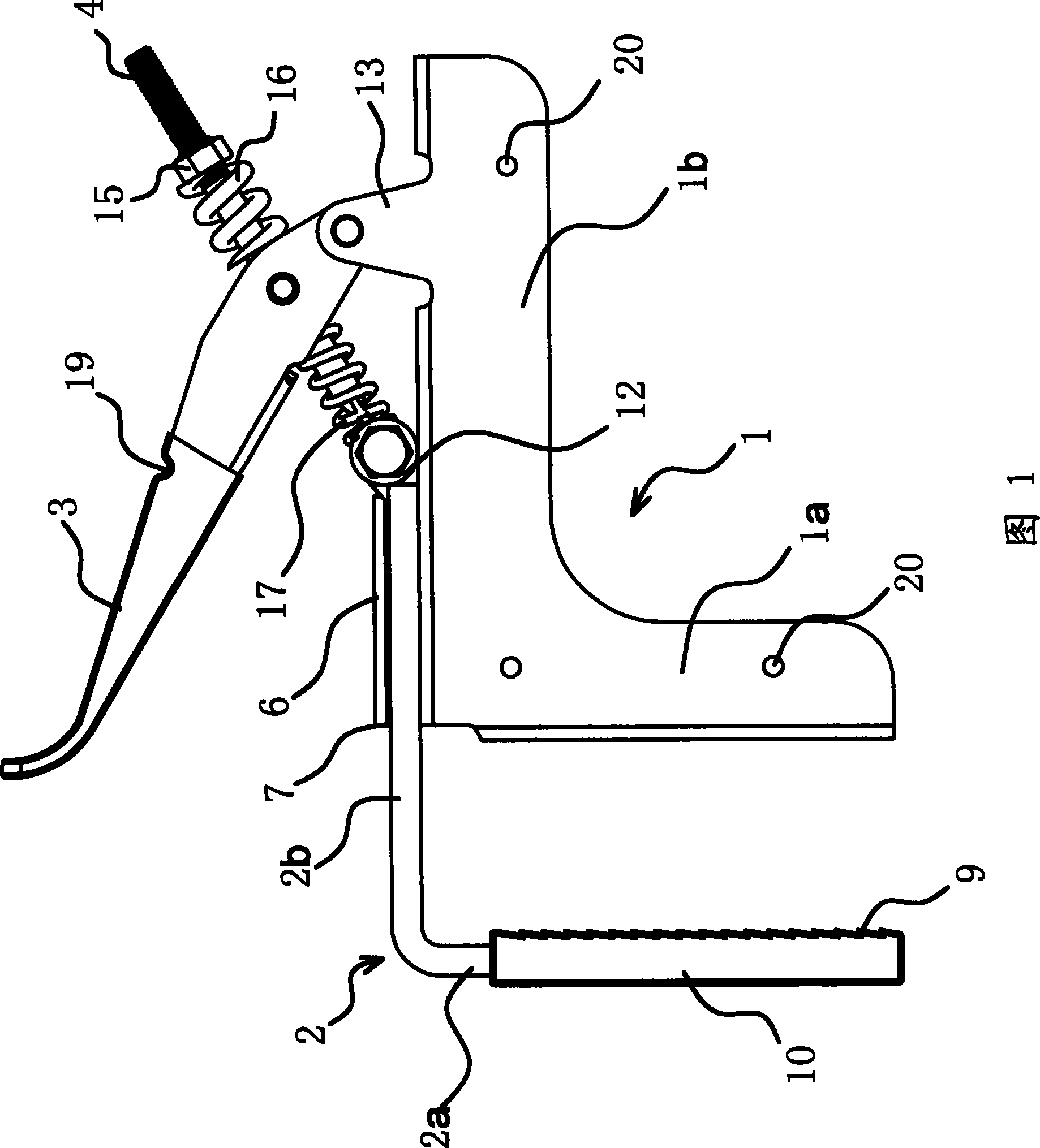
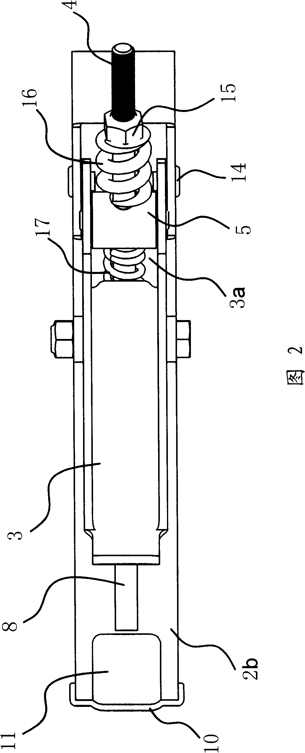
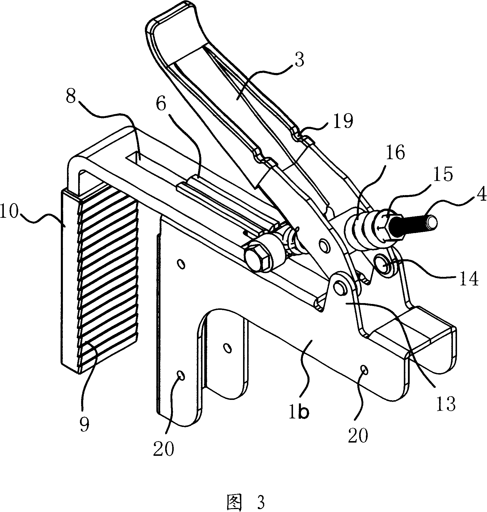
[0039] In the figure, bracket 1, static clamping piece 1a, positioning piece 1b, splint 2, moving clamping piece 2a, connecting piece 2b, handle 3, square groove 3a, sliding rod 4, sliding block 5, connecting plate 6, opening chute 7 , strip groove 8, friction increasing tooth 9, plastic sleeve 10, reinforcing rib 11, rolling hole 12, hinged ear body 13, pivot 14, lock nut 15, large spring 16, small spring 17, square tube 18, semicircle Hole 19, connecting hole 20.
[0040] As shown in Figures 1 and 2, this F-shaped cargo clip includes parts such as support 1, splint 2, handle 3, slide bar 4, slide block 5, compression spring (comprising a large spring 16 and a small spring 17).
[0041] The bracket 1 is L-shaped and is composed of a static clip 1a and a positioning piece 1b connected as one. The splint 2 is also L-shaped, and is composed of a movable clip 2a and a connecting piece 2b connected as one. The connecting piece 2b is slidably coupled to the positioning piece 1b s...
PUM
 Abstract
Description
Claims
Application Information
 - R&D
- Intellectual Property
- Life Sciences
- Materials
- Tech Scout
- Unparalleled Data Quality
- Higher Quality Content
- 60% Fewer Hallucinations
Browse by: Latest US Patents, China's latest patents, Technical Efficacy Thesaurus, Application Domain, Technology Topic, Popular Technical Reports.
© 2025 PatSnap. All rights reserved.Legal|Privacy policy|Modern Slavery Act Transparency Statement|Sitemap|About US| Contact US: help@patsnap.com


