Bearing support structure for turbomolecular pump

A technology of turbomolecular pump and bearing support, applied in the direction of rotating bearing, bearing, rigid support of bearing parts, etc., can solve the problem of bearing overheating, bearing outer ring inclination to limit bearing damage, and difficulty in transferring heat from rotating shaft bearings, etc. problems, to improve bearing durability, reduce operating noise and vibration, and achieve the effect of long life

Inactive Publication Date: 2007-05-30
OSAKA VACUUM
View PDF3 Cites 18 Cited by
  • Summary
  • Abstract
  • Description
  • Claims
  • Application Information

AI Technical Summary

Problems solved by technology

[0016] According to the invention of the above-mentioned Patent Document 1, there is a problem in that a set of ball bearings is embedded with a slight gap in the bearing bush in which the outer peripheral portion of the ball bearing is fitted, and the sleeve (sleeve) is fitted with a slight gap. The method is embedded in the round hole of the bushing shell fixed on the shell, because the vibration absorption of the above-mentioned ball bearing by the two circumferential gaps is not sufficient
[0017] Furthermore, in the technology of the above-mentioned Patent Document 2, since the bearing is supported by the housing via the elastic support ring, there is a problem that the heat of the rotating shaft and the bearing part is difficult to transfer to the housing side, causing the bearing to overheat.
Furthermore, when the elasticity of the elastic supporting ring supporting the bearing is weak, there is a problem that the rotating shaft cannot be supported on the correct axis, and the tip

Method used


Image

  • Bearing support structure for turbomolecular pump
  • Bearing support structure for turbomolecular pump
  • Bearing support structure for turbomolecular pump

Examples


Embodiment 1

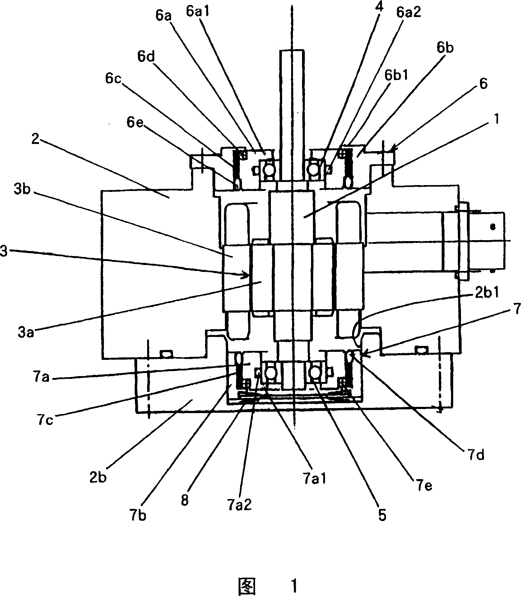
[0031] Fig. 1 is a longitudinal sectional view of a part of a turbomolecular pump having a bearing support structure of the present invention, a bearing support part, in which the rotor clamped on the upper part of the rotating shaft 1 and the rotor continuously arranged on the upper part of the intermediate housing 2 are omitted in this Fig. 1 the upper shell.

[0032] 3 denotes a motor, and the motor 3 includes a rotor 3 a fixed to the outer peripheral portion of the rotating shaft and a stator 3 b fixed to the inner peripheral portion of the intermediate case 2 .

[0033] Reference numerals 4 and 5 denote ball bearings, and the ball bearings 4 and 5 are provided above and below the motor 3 with the motor 3 interposed therebetween. These ball bearings 4 and 5 are self-lubricating types filled with grease.

[0034] 6 denotes a first bush, and the first bush 6 has an inner and outer double structure including an inner first bush 6 a on the inner peripheral side and an outer fi...
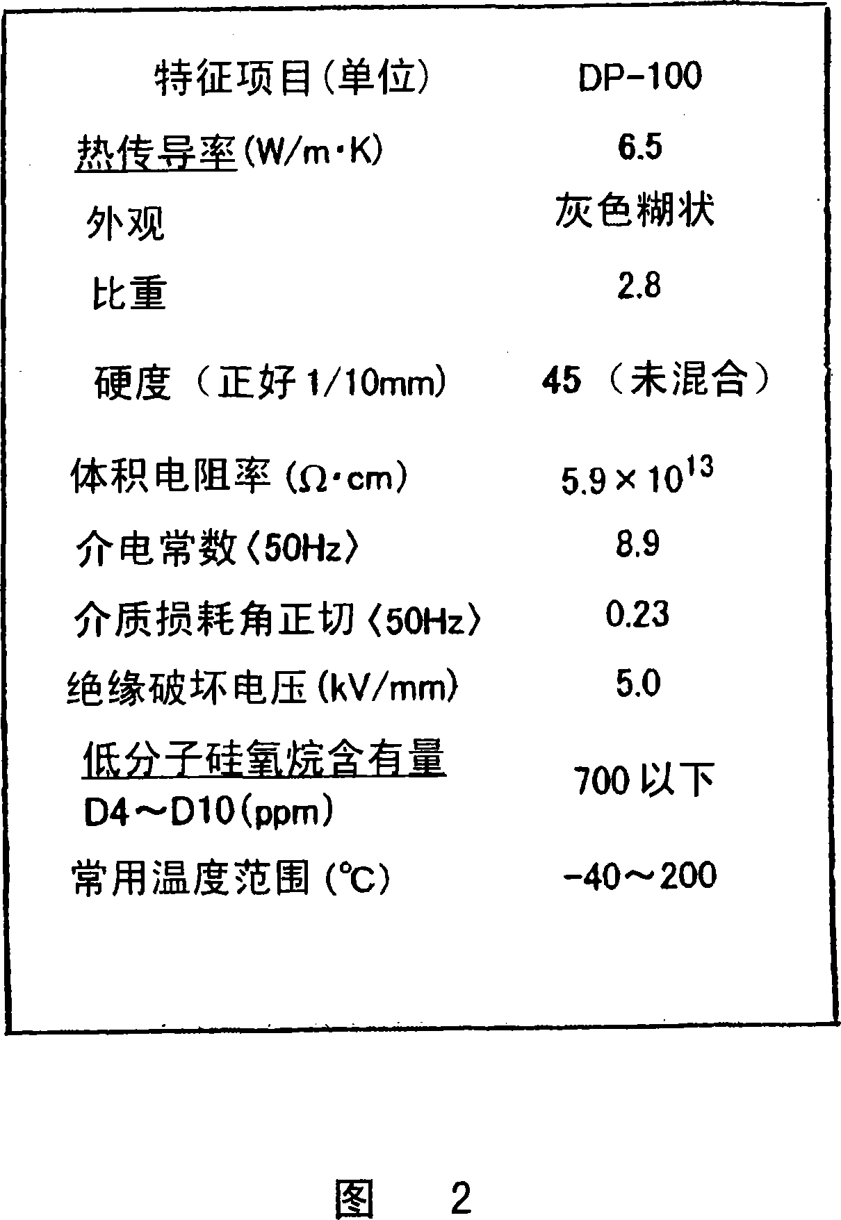

PUM

PropertyMeasurementUnit
Thermal conductivityaaaaaaaaaa

Abstract

A bearing support structure for a turbomolecular pump, capable of absorbing fine vibration occurring in a bearing section in a turbomolecular pump of a type in which a rotation shaft of a rotor is supported by rolling bearings, capable of cooling heat produced at the bearing section, having long life, and being safe. A bearing support structure for a turbomolecular pump, where ball bearings (4, 5) for supporting a rotation shaft (1) are fitted in position so as to be in contact with an upper first sleeve (6) and a lower second sleeve (7), respectively, at the outer periphery and one end surface of each of the bearings (4, 5). The first sleeve (6) and the second sleeve (7) are each formed in a double structure constructed from an inner sleeve and an outer sleeve, and gel layers (6c, 7c) having predetermined heat conductivity are provided between the inner sleeve and the outer sleeve. In front and rear of the gel layers (6c, 7c), there are provided O-rings (6d, 6e) and O-rings (7d, 7e) to seal up the gel layers (6c, 7c).

Description

technical field [0001] The present invention relates to a turbomolecular pump with a rotor rotating at a high speed and used in a pressure range from medium vacuum to ultra-high vacuum, and particularly relates to a method in which the rotating shaft of the rotor is supported by upper and lower rolling bearings lubricated with grease Bearing support structure of a turbomolecular pump. Background technique [0002] FIG. 3 is a longitudinal sectional view showing an example of a conventional turbomolecular pump. [0003] That is, in FIG. 3 , a represents the rotor of the turbomolecular pump, b represents the rotating shaft, and c represents the motor. [0004] The rotating shaft b and the rotor a are rotated at a high speed by the drive of the motor c, air is sucked in from the suction port d, and exhausted from the exhaust port e. [0005] The rotating shaft b is pivotally supported in the housing h by the upper first ball bearing f and the lower second ball bearing g. [...

Claims


Application Information

Patent Timeline
IPC IPC(8): F04D19/04F16C27/06F16C37/00
CPCF16C27/06F16C37/00F16C35/077F04D29/668F04D29/5853F04D29/059F04D19/042F16C2360/45
Inventor 井口昌司上原孝浩中辻重义
Owner OSAKA VACUUM
Why Eureka
Try Eureka