
Image display apparatus and in -vehicle image display apparatus

An image display and image technology, applied in identification devices, control devices, projection devices, etc., can solve problems such as differences in illumination intensity, reduced focus, and uneven illumination

Inactive Publication Date: 2007-05-30
OLYMPUS CORP
View PDF1 Cites 23 Cited by
  • Summary
  • Abstract
  • Description
  • Claims
  • Application Information

AI Technical Summary

Problems solved by technology

[0006] However, in the three-dimensional display device of the time-sharing lighting method disclosed in Japanese Patent No. 3072866, there is a problem that the range that can be properly observed is narrow, especially when the observer on the R side observes the image on the R side. , when the observation position is moved to the R side, the L side image, which is an image in the opposite direction, is observed
[0008] In addition, in an optical system using a biconvex lens, there is a problem that when separating the left and right images at a large angle, the focal length must be reduced, and the curvature becomes large, and at the same time, the influence of aberration increases, so The effect of the final crosstalk becomes larger
[0009] On the other hand, in the scanning backlight method, there is a problem that two light sources 152-1, 152-2 correspond to one light guide plate 153, and the left and right directions are switched by turning on / off each light source 152-1, 152-2. Therefore, the structure of the light guide plate 153 must be a structure with the same surface processing or a left-right symmetrical structure. Variations in illumination intensity, which are observed as uneven illumination, especially on larger displays
[0010] In addition, due to the "raster scan" which is the driving method used in ordinary liquid crystal panels, and the "holding characteristics" which are the display characteristics of liquid crystal panels, the image of each pixel is continuously displayed for a fixed period (1 / 60 second, etc.), When the directivity of a surface light source of the same size as the screen size is switched at the same time, there is a problem that the lighting time is limited and crosstalk is likely to occur

Method used


Image

  • Image display apparatus and in -vehicle image display apparatus
  • Image display apparatus and in -vehicle image display apparatus
  • Image display apparatus and in -vehicle image display apparatus

Examples


Embodiment Construction

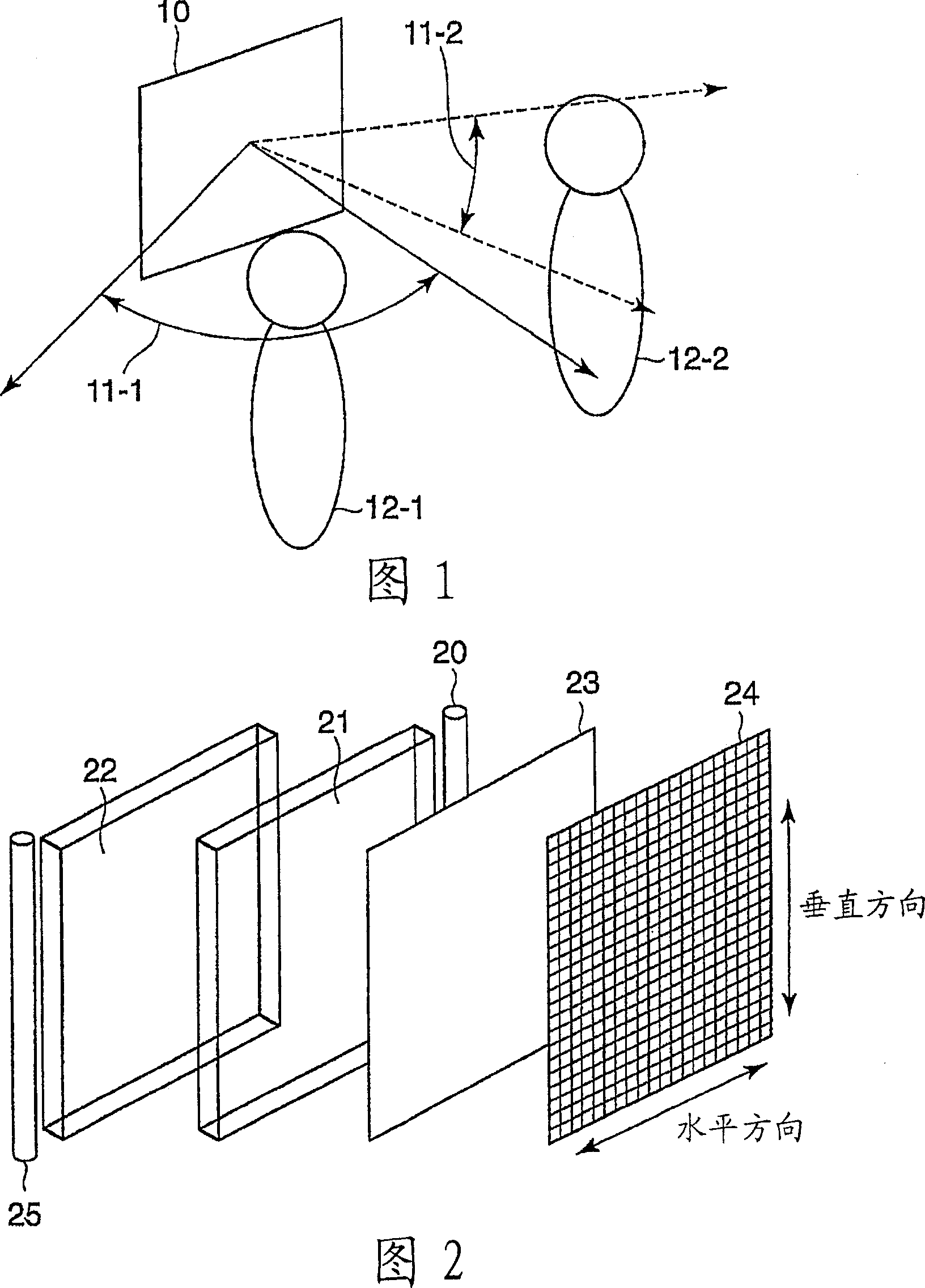
[0051] Hereinafter, embodiments of the present invention will be described in detail with reference to the drawings. FIG. 1 is a diagram for explaining an example of use of the video display device of the present invention. The first observer 12 - 1 viewing the display screen 10 from the left side is located in the front right of one display screen 10 , and the second observer 12 - 2 viewing the display screen 10 from the right side is located in the front left side of the display screen 10 . Since the first observer 12-1 is located in the first image observation range 11-1, and the second observer 12-2 is located in the second image observation range 11-2, they can respectively observe the first image and the second image at the same time. image.

[0052] 2 is a diagram showing the basic structure of the video display device of the present invention, in which a transmissive display element 24, a light diffusing element 23, a first light guide plate 21, and a second light gui...


PUM


Abstract

A video display having one display screen capable of displaying video images corresponding to a plurality of viewers, respectively. The video display comprises an illuminating section emitting first and second light beams, respectively, toward at least two different directions in a time sharing way, and a transmission display element capable of displaying first and second video images by using first and second light beams emitted from the illuminating section as illuminating light in a time sharing way. The illuminating section comprises a first light source (20) emitting the first light beam, a second light source (25) emitting the second light beam, a first light guide plate (21) emitting the first light beam from the first light source (20) only in the direction of a first viewer, and a second light guide plate (22) emitting the second light beam from the second light source (25) only in the direction of a second viewer.

Description

technical field [0001] The present invention relates to an image display device and an in-vehicle image display device. Background technique [0002] Conventionally, a video display device having one display surface and capable of viewing video corresponding to each viewing direction is known. For example, Japanese Patent No. 3072866 discloses a stereoscopic display device using matrix lighting, lenticular lenses, etc. . [0003] (A) and (B) of FIG. 19 are diagrams showing an example of a configuration of a conventional image display device, and a light source group 100 composed of divided light sources L1, R1 to L3, and R3 such as strip light sources and matrix light sources, etc. , and the combination of the lenticular lens 101, which is a light diffusing element composed of the lenses 1 to 3, performs time-sharing illumination. In FIG. 19(A), among L1, R1 to L3, and R3, the light sources of R1 to R3 are turned on, and the light sources of L1 to L3 are turned off. In a...

Claims


Application Information

Patent Timeline
Patent Type & Authority Applications(China)
IPC IPC(8): G02B27/22B60R11/02F21V8/00G02B6/00G02F1/13G02F1/13357G03B35/26G09F9/00G02F1/1335
CPCB60K35/00B60K2350/206G02B6/0048B60K2350/2052G09F9/305G02B6/0038B60K2350/901G02B6/0076B60K2350/903G02B6/0068G03B21/625G02B6/003G02B27/2264G02B6/0016G02B30/24B60K2360/20B60K2360/334B60K35/656B60K35/654B60K35/22B60K35/60B60K35/81
Inventor 杉原良平井场阳一
Owner OLYMPUS CORP
Learn More