Image displaying apparatus

An image display device and image technology, applied in the direction of static indicators, instruments, etc., can solve the problem of improving the effect of dynamic image blurring, and achieve the effect of improving the effect of dynamic image blurring

Inactive Publication Date: 2007-06-06
HITACHI DISPLAYS
View PDF1 Cites 13 Cited by
  • Summary
  • Abstract
  • Description
  • Claims
  • Application Information

AI Technical Summary

Problems solved by technology

Therefore, in the prior art, when the original frame is of high grayscale, the improvement effect of the dynamic image blur is small

Method used


Image

  • Image displaying apparatus
  • Image displaying apparatus
  • Image displaying apparatus

Examples


Embodiment 1

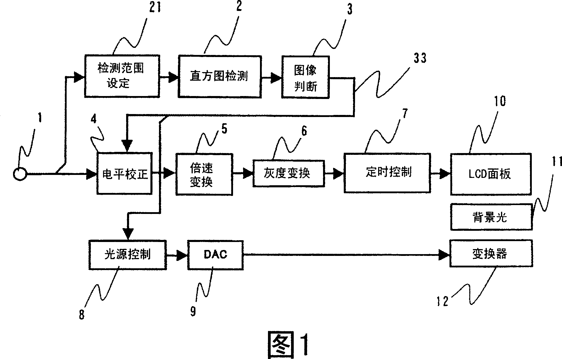
[0032] FIG. 1 is a block diagram showing a configuration example of the first embodiment of the image display device of the present invention. In this embodiment, it is assumed that an image signal in a component format (YcbCr format) having a frame frequency of 60 Hz is input from the input terminal 1 . The image signal input to the input terminal 1 is supplied to the level correction unit 4 . In addition, the input image signal is also supplied to the histogram detection unit 2 via the detection range setting unit 21 . The detection range setting unit 21 sets the range of the brightness histogram detected by the histogram detection unit on the screen of the image 1 (details will be described later). The histogram detection unit 2 detects, for example, a luminance histogram in one frame or one field period from a luminance signal (Y) included in an input image signal. The luminance histogram represents the frequency of appearance of luminance signals corresponding to each o...

Embodiment 2

[0058] Next, a second embodiment of the present invention will be described. This embodiment, as shown in FIG. 8 , is characterized in that a gradation correction unit 21 is newly provided on the level correction circuit 4 , and the gradation correction unit 121 is controlled by a control signal 122 . The structure other than the level correction circuit 4 is the same as that of the first embodiment. Next, details of the present invention will be described. In addition, in FIG. 8, the same code|symbol is attached|subjected to the same component as the component of FIG. 4, and description is abbreviate|omitted.

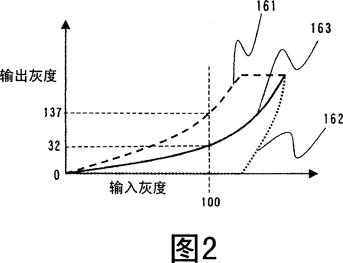
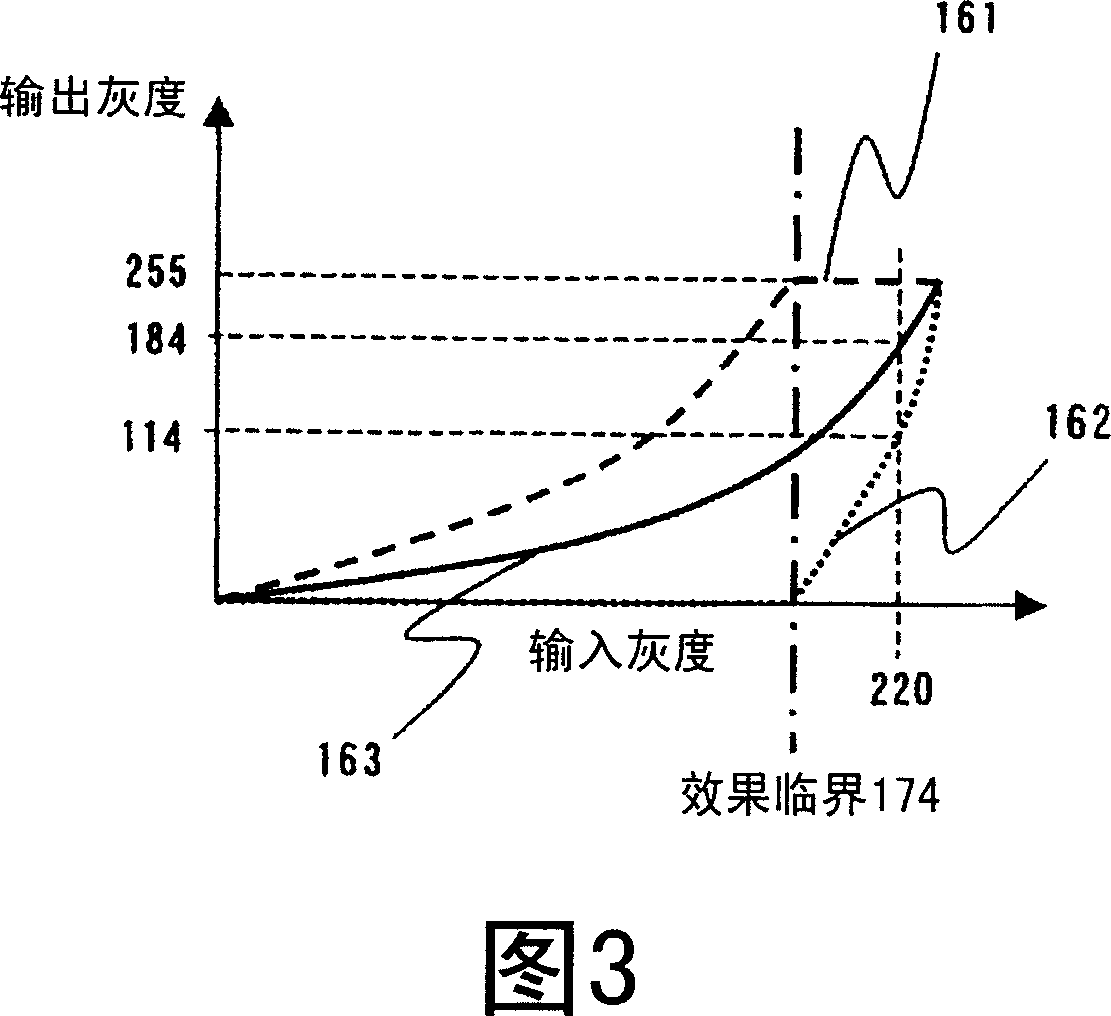
[0059] This embodiment is used to reduce the loss of dark parts through the black level correction performed by the black level correction unit 31 when the amplitude of the input image extends from high grayscale to low grayscale in a wide range. Therefore, the present embodiment provides the gradation correction section 121 for compressing the signal amplitude in th...

Embodiment 3

[0066] Next, a third embodiment of the present invention will be described. FIG. 12 is a block diagram showing a configuration example of an image display device according to a third embodiment of the present invention. In FIG. 4 , the same reference numerals are assigned to the same components as those of the first embodiment shown in FIG. 1 , and detailed description thereof will be omitted.

[0067] In this embodiment, the signal based on the above-mentioned grayscale division method is suppressed for an image signal after 2-3 pull-down or 2-2 pull-down processing (hereinafter, these are collectively referred to as “pull-down signals”) such as movies, CG, and animation as input images. Handled cases of flickering and jittering. Before describing this embodiment, the reason why flicker and jitter occur when the pull-down signal is subjected to signal processing based on the gradation division method will be described.

[0068] For example, if the signal processing is perfo...


PUM

PropertyMeasurementUnit
greyscaleaaaaaaaaaa

Abstract

An image displaying apparatus, for improving motion blur, in particular, on an image displaying apparatus of hold-type, such as, a liquid crystal display element, etc., comprising: sub-frame producing portions (5, 6) for producing a first sub-frame, a second sub-frame being lower in the gradation than the first sub-frame, from an image of one frame of an image signal inputted; a histogram detection portion (2) for detecting brightness histogram of the image signal; an image determination portion (3) for determining on whether the image signal inputted is a high-gradation image or not, from that brightness histogram; and a level compensation portion (4) for lowering a gradation level of that image signal inputted. And, according to the present invention, lowering the gradation of the high-gradation image keeps the difference in brightness between the first and the second sub-frames, and thereby increasing an effect of improving the motion blur.

Description

technical field [0001] The present invention relates to an image display device using a hold-type display element such as a liquid crystal display element. Background technique [0002] Hold-type display elements such as liquid crystal display elements hold image data for each pixel during one frame period, unlike impulsive-type display elements such as CRTs. Therefore, when a moving image is displayed using such a display device, a phenomenon in which the outline of the image appears blurred (hereinafter referred to as moving image blur) occurs, and the user sees an afterimage. [0003] A technique for improving such moving image blur is known, for example, in Japanese Patent Laid-Open No. 2005-173573. Paragraph 0012 and FIG. 1 of Japanese Unexamined Patent Application Publication No. 2005-173573 discloses a technology in which, in a hold-type image display device, one frame period is divided into a plurality of subframe periods with different gradations from each other, a...

Claims


Application Information

Patent Timeline
Patent Type & Authority Applications(China)
IPC IPC(8): G09G3/36G02F1/133
CPCG09G3/2025G09G2310/061G09G2360/16G09G3/3406G09G2320/064G09G3/3611G09G2340/0435G09G2320/0646G09G2320/0271G09G2320/0261G09G2320/0633
Inventor 荻野昌宏甲展明小野记久雄盛育子大石纯久
Owner HITACHI DISPLAYS
Why Eureka
Try Eureka