Radiating structure for communicating machine

A technology for machines and communication circuits, applied in cooling/ventilation/heating renovation, rack/frame structure, electrical equipment structural parts, etc., can solve problems such as inability to guarantee electrical characteristics

Inactive Publication Date: 2007-06-06
MITSUBISHI ELECTRIC CORP
View PDF0 Cites 4 Cited by
  • Summary
  • Abstract
  • Description
  • Claims
  • Application Information

AI Technical Summary

Problems solved by technology

[0013] Even in such a configuration, the heat generated by the heating element 1 can be released through the shielding plate 3, but in this prior art example, since the metal material is installed near the semiconductor component, there is a problem that the electrical characteristics cannot be guaranteed, and the use of The problem that the L-shaped metal body cannot sufficiently diffuse the heat in the 3 planes of the shielding plate

Method used


Image

  • Radiating structure for communicating machine
  • Radiating structure for communicating machine
  • Radiating structure for communicating machine

Examples


Embodiment 1

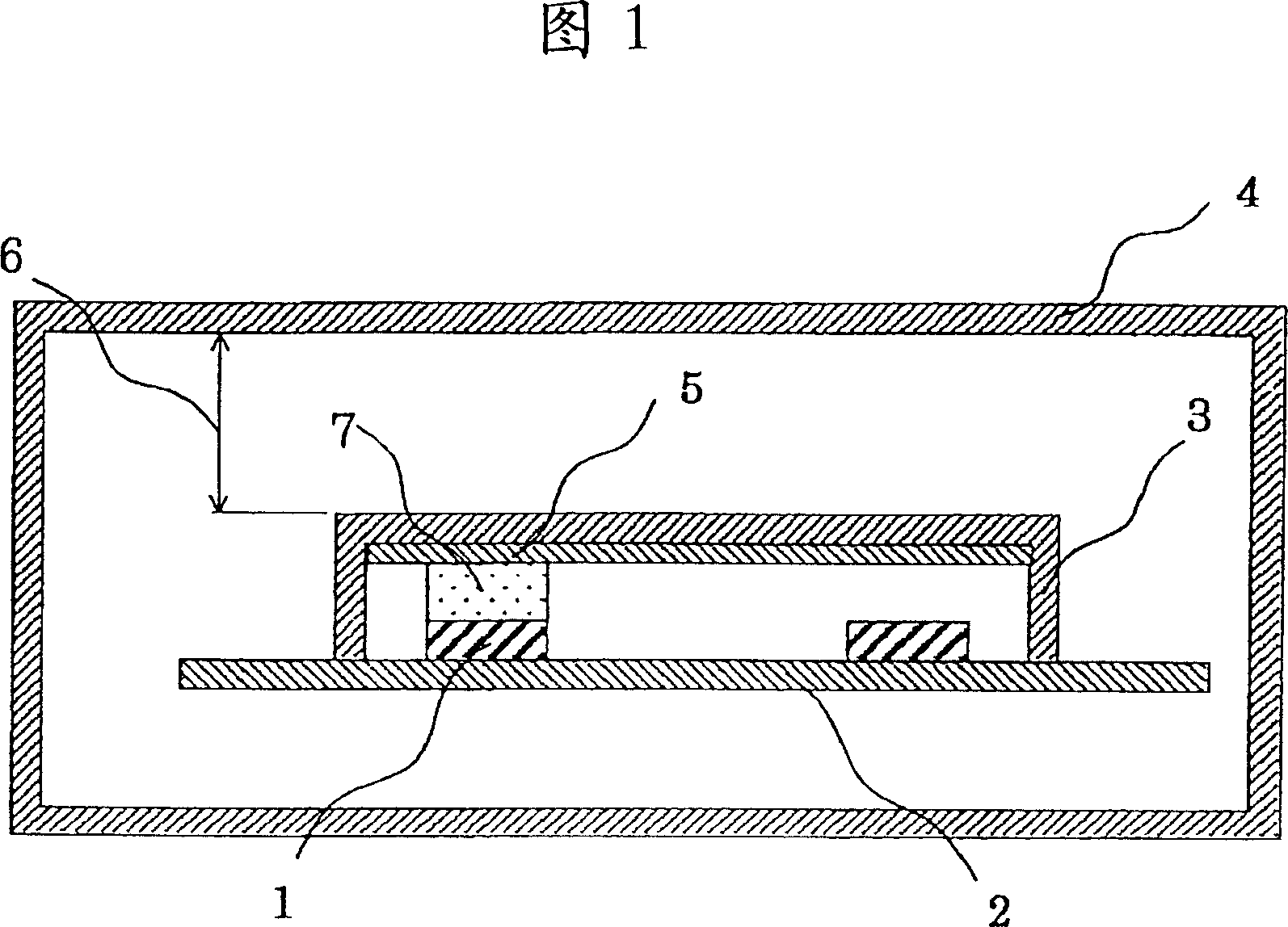
[0027] Fig. 1 is a cross-sectional configuration diagram showing the main configuration of a portable communication device according to Embodiment 1 of the present invention. In this figure, 1 is a heat generating element (hereafter referred to as a heat generating element), 2 is a printed circuit board on which a communication circuit having a heat generating element 1 is mounted, and 3 is a circuit board for suppressing the incidence of noise caused by electromagnetic waves from the outside, covering communication The resin shielding case 4 of the circuit is a housing for accommodating the shielding case 3 and the printed circuit board 2 . 5 is a heat dissipation fin (thermal diffusion member) installed along the inner wall of the shield box 3 for thermal diffusion in the surface direction. As the material of the heat sink 5, in addition to metal sheets with high thermal conductivity, such as Al (thermal conductivity: 236W / mK) and copper (thermal conductivity: 403W / mK), it i...

Embodiment 2

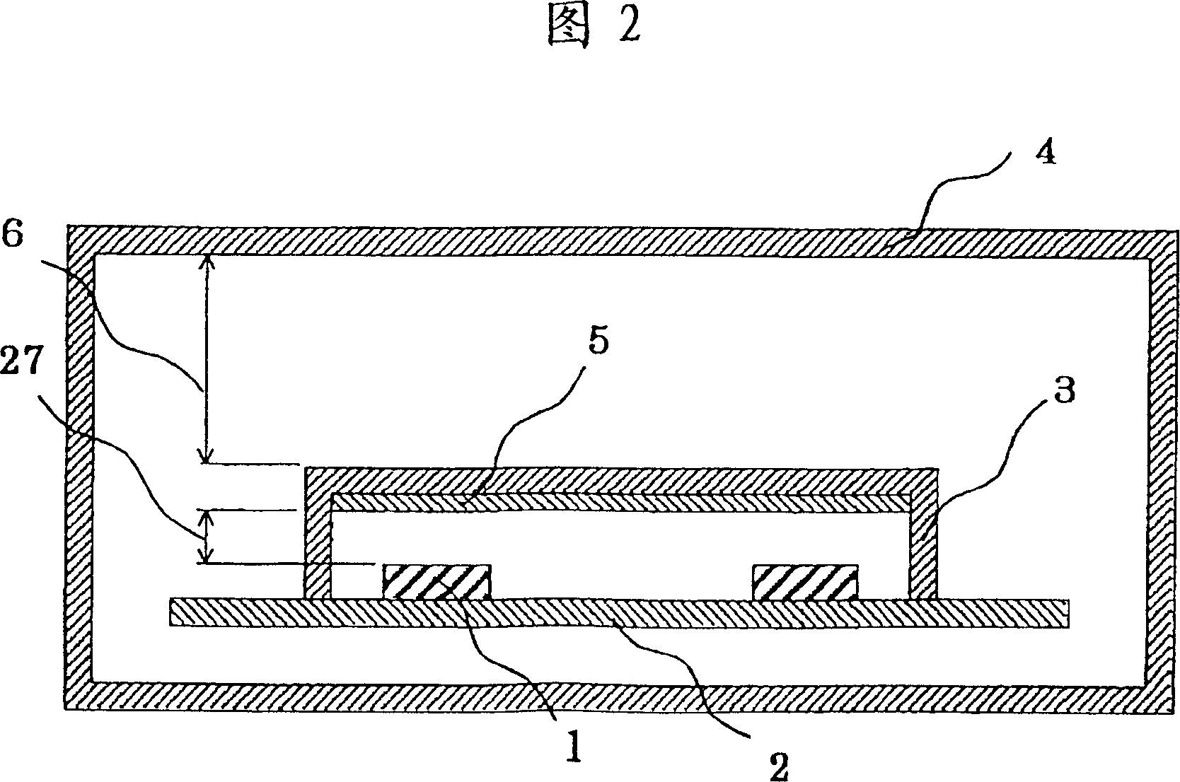
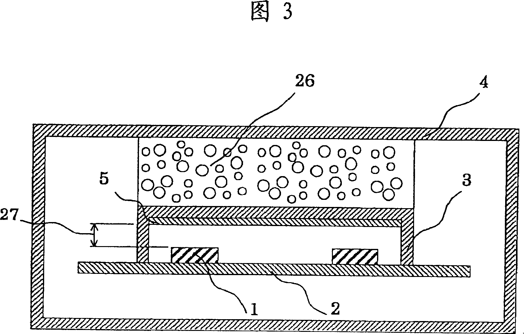
[0064] Fig. 2 is a cross-sectional configuration diagram showing the main configuration of a portable communication device according to Embodiment 2 of the present invention, and Fig. 3 is a cross-sectional configuration diagram showing the main configuration of another portable communication device according to Embodiment 2 of the present invention. 2 is an example of ensuring an air layer as the heat insulating layer 6, and FIG. 3 is an example of providing a foam material 26 as the heat insulating layer 6.

[0065] In the 2nd figure, among the 3rd figure, 27 is an air layer. In Embodiment 2, no thermally conductive sheet 7 is provided between the heat sink 5 and the heating element 1 , and an air layer 27 is formed between the heat sink 5 and the heat generating element 1 . When the calorific value of the heating element 1 is small, as long as the heat sink 5 is installed on the inner wall of the shielding box 2, the temperature of the heating element can be fully reduced b...

Embodiment 3

[0068] Fig. 4 is a cross-sectional configuration diagram showing the main configuration of a portable communication device according to Embodiment 3 of the present invention. In this figure, 33 is a metal shielding box. In this embodiment, the shielding box is made of metal material, so that the metal shielding box 33 has the function of the heat sink 5 in the first embodiment. The thermal conductive sheet 7 is installed between the heating element 1 and the inner wall of the metal shielding box, and the air layer 6 is between the metal shielding box 33 and the housing 4 .

[0069] By doing so, the same effect as that of the first embodiment is obtained, and since the attachment of the heat sink can be omitted, the effect of reducing the assembly cost can be obtained.


PUM


Abstract

A heat radiation structure of communication machine consists of communication circuit being set on printed circuit base plate and being set with heating element, shielding box covering communication circuit and suppressing the incoming electromagnetic wave on said communication circuit from outside, shell for containing said shielding box and printed circuit base plate in, heat radiation component being set along internal wall of shielding box and being used to carry out surface heat radiation, and heat isolation layer set between shielding box and shell.

Description

[0001] This application is a divisional application of the patent application with the application number 00812651.8, the application date being March 8, 2002, and the invention title being "radiation structure of communication equipment". technical field [0002] The present invention relates to a communication device, and specifically relates to a heat dissipation structure for dissipating heat generated by an exothermic element arranged in a housing. Background technique [0003] Conventional electronic devices such as portable communication devices have a heat dissipation function for dissipating heat generated by built-in heat generating elements, as shown in FIG. 17, for example. FIG. 17 is a cross-sectional view showing the main structure of a conventional portable communication device shown in Japanese Patent Publication No. 11-204970 published in 2011. In this figure, 1 is a heat generating element (hereinafter referred to as a heat generating element), 2 is a print...

Claims


Application Information

Patent Timeline
Patent Type & Authority Applications(China)
IPC IPC(8): H05K7/20H05K7/18H05K9/00
CPCH05K9/0024H05K7/20445H05K9/0026
Inventor 下地美保子尾崎永一中尾一成大串哲朗平尾康一长谷川学小林孝吉沢二郎
Owner MITSUBISHI ELECTRIC CORP
Why Eureka
Try Eureka