Method and apparatus for lubricating cylinder surfaces in large diesel engines

A lubricating device and lubricating oil technology, which is applied in the field of lubricating systems, can solve problems such as high external injection pressure, and achieve the effect of a simple system

Active Publication Date: 2010-06-02
HANS JENSEN LUBRICATORS
View PDF8 Cites 0 Cited by
  • Summary
  • Abstract
  • Description
  • Claims
  • Application Information

AI Technical Summary

Problems solved by technology

[0014] With regard to conventional cylinder wall lubrication, the practice to date has been to use a simple spring biased check valve against the pressure inside the cylinder, however this is subject to the higher external injection pressure

Method used


Image

  • Method and apparatus for lubricating cylinder surfaces in large diesel engines
  • Method and apparatus for lubricating cylinder surfaces in large diesel engines
  • Method and apparatus for lubricating cylinder surfaces in large diesel engines

Examples


Embodiment Construction

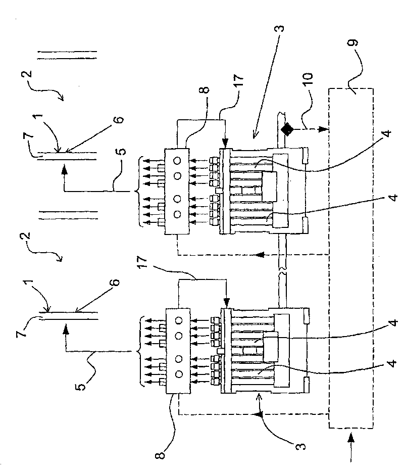
[0052] figure 1 Shown is an apparatus for lubricating the cylinder inner surface 1 of a cylinder 2 of a large diesel engine. The apparatus shown comprises two lubricating devices 3 each having a series of piston pumps indicated at 4 . Via connecting pipes 5 (only one is shown for each lubricating device), each piston pump is connected to a lubrication point 6 provided in the cylinder wall 7 for lubricating the cylinder inner surface 1 of the cylinder wall. The device also includes a flow regulator 8, which will refer to figure 2 Describe in detail.

[0053] Furthermore, the device comprises an electronic control unit 9 connected to the flow regulator 8 and the lubricating device 3 . As indicated at 10 , the flow regulator may receive an indication signal from the lubricating device 3 .

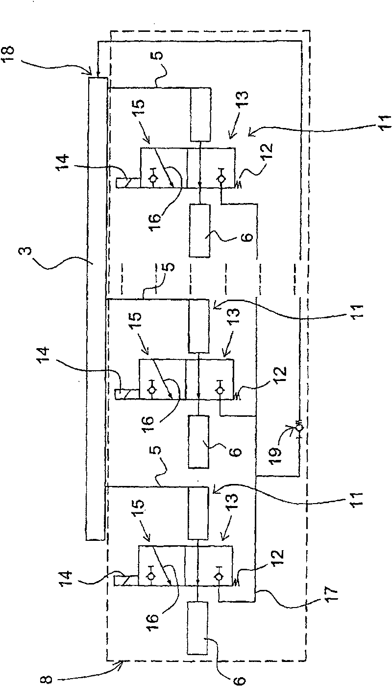
[0054] figure 2 is a schematic diagram of the flow regulator 8 . figure 2 Three lubrication points 6 and a lubrication device 3 are shown. This state therefore shows that there are t...


PUM


Abstract

There is described a method and an installation for lubricating cylinder surfaces 6 in large diesel engines. The installation includes a lubricating apparatus 3 with a number of piston pumps 4 which via connecting lines 5 are connected with lubricating points 6 in the cylinder walls 7. In order to enable electronically controlled regulation of the lubricating oil portion, there is provided an electronic control unit 9 which is connected with a flow regulator 8. The flow regulator includes redirecting valves 12 which are inserted in connecting lines 5 between the lubricating apparatus 3 and thelubricating points 6.

Description

technical field [0001] The present invention relates to a lubricating system comprising a method and a device for lubricating the inner surface of a cylinder of a large diesel engine, in particular a marine engine, comprising at least one lubricating device having a plurality of piston pumps connected to the cylinder via connecting pipes The different lubrication points in the wall are connected together and supplied with lubricating oil. Background technique [0002] The lubricating devices are usually designed as pump devices, which are fitted tightly to the respective cylinder and are connected to a reservoir for lubricating oil and to lubrication points in the form of oil spray nozzles at various points on the cylinder wall. Each pump unit comprises a plurality of piston pumps supplying lubricating oil to different lubricating points, and they are driven by a common rotating control shaft on which a cam is applied. As the shaft rotates, the cam with the extrusion head a...

Claims


Application Information

Patent Timeline
Patent Type & Authority Patents(China)
IPC IPC(8): F01M1/14F01M1/16F01M3/04F01M1/08
CPCF01M1/16F01M2001/083F01M1/14F01M3/04
Inventor 扬·奥曼
Owner HANS JENSEN LUBRICATORS
Why Eureka
Try Eureka