Electromechanical part of rotary compressor

A rotary compressor and mechanical technology, applied in the direction of magnetic circuit rotating parts, magnetic circuit static parts, magnetic circuit shape/style/structure, etc., can solve the problem of low speed and maximum torque, unreasonable magnetic field distribution, and inefficiency Achieving optimality and other issues, to achieve optimal efficiency, reasonable distribution of the magnetic field, and the effect of increasing the speed

Inactive Publication Date: 2007-06-13
LG ELECTRONICS (TIANJIN) APPLIANCES CO LTD
View PDF0 Cites 1 Cited by
  • Summary
  • Abstract
  • Description
  • Claims
  • Application Information

AI Technical Summary

Problems solved by technology

However, the electromechanical part of this prior art rotary compressor has the following problems: because the number of stator slots 13 on the stator 11 in this electromechanical part is small, and the height of the rotor slot 14 on the rotor 12 is low, so this The structure is not conducive to the distribution of the coil, so the magnetic field distribution is unreasonable, resulting in low speed and maximum torque, and as a result, the efficiency cannot be optimized

Method used


Image

  • Electromechanical part of rotary compressor
  • Electromechanical part of rotary compressor

Examples


Embodiment Construction

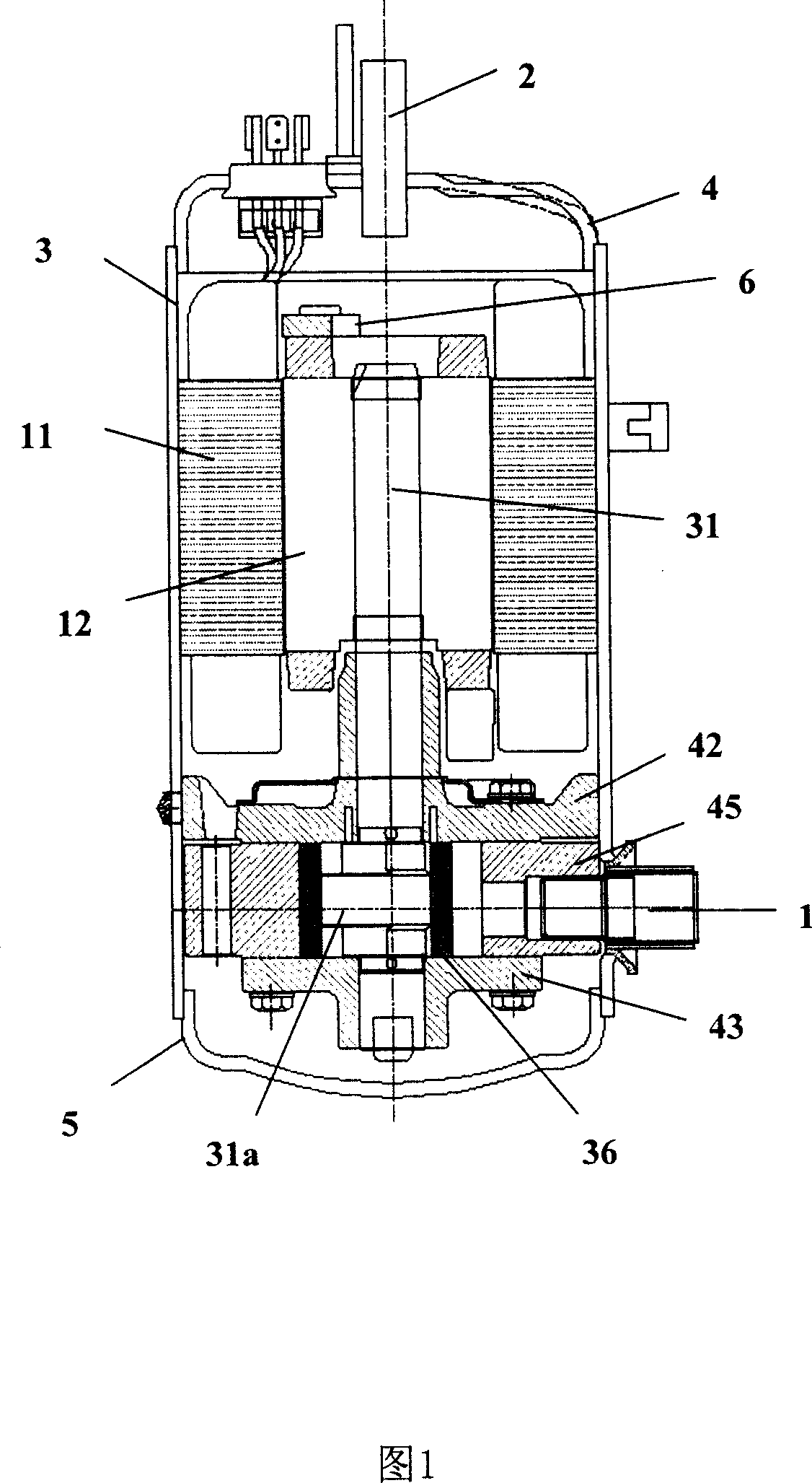
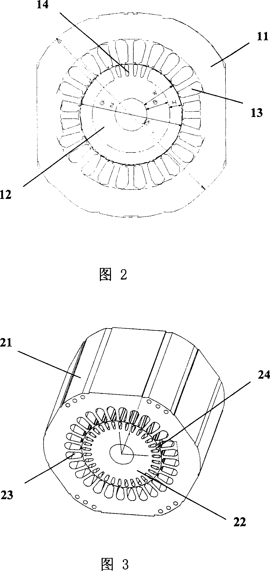
[0011] As shown in Fig. 3 and Fig. 1, the electromechanical part of the rotary compressor provided by the present invention is mainly composed of a stator 21 fixed on the inner wall of the cylindrical shell 3 and a motor which is located at the center of the stator 21 and can pass between the stator 21. The rotor 22 is composed of a rotor 22 that rotates by electromagnetic action; the stator 21 is in a tubular structure, and 28 stator slots 23 are formed in radial depressions on its inner circumference; A plurality of rotor slots 24, the height of each rotor slot 24 is 11mm. The number of rotor slots 24 on the rotor 22 is the same as that of the prior art. When the rotary compressor provided by the present invention is in operation, the rotor 22 located at the upper center of the airtight container will rotate at a high speed through the electromagnetic interaction with the stator 21, and at the same time drive the crankshaft 31 that runs through its center and the lower part ...


PUM


Abstract

The electromechanical part is mainly composed of stator fixed on inner wall of cylindrical shell, and rotor located at center of the stator. Being in tubular structure, the stator includes 28 pieces of stator slots depressed on inner circle face. Rotor is in shape of cylinder. Multiple rotor slots are impenetrated to excircle circumference and distributed in rediatiform. Height of each rotor slot is 11mm. Number of stator slot is increased to 28 pieces from 24 pieces, and height of rotor slot is increased in the invention. Thus, magnetic field is distributed more reasonably, and rotating speed, and maximum torque are raised so as to reach optimal efficiency.

Description

technical field [0001] The present invention relates to a rotary compressor, in particular to an electromechanical part of a rotary compressor capable of making the magnetic field distribution more reasonable. Background technique [0002] In general, a compressor is a machine that compresses a fluid. This compressor is composed of a closed container with a certain internal space, an electromechanical part installed in the closed container to generate a driving force, and a compression mechanical part that can compress fluid by using the driving force of the electromechanical part. Fig. 1 is a sectional view of the longitudinal structure of a prior art rotary compressor. As shown in FIG. 1, the airtight container of this prior art rotary compressor consists of a cylindrical casing 3, an upper cover 4 and a lower cover 5. As shown in FIG. A refrigerant inlet 1 is provided on one side of the casing 3 , and a refrigerant outlet 2 is vertically provided at the center of the up...

Claims


Application Information

Patent Timeline
Patent Type & Authority Applications(China)
IPC IPC(8): H02K1/16H02K1/22
Inventor 李玉强
Owner LG ELECTRONICS (TIANJIN) APPLIANCES CO LTD
Why Eureka
Try Eureka