
Drying apparatus and method

A kind of drying equipment and drying technology, which is applied in the field of metal beverage container drying equipment and metal beverage container drying, and can solve the problems of can metal damage, raising the temperature of the dryer, etc.

Inactive Publication Date: 2007-06-13
GREENBANK TECH
View PDF0 Cites 12 Cited by
  • Summary
  • Abstract
  • Description
  • Claims
  • Application Information

AI Technical Summary

Problems solved by technology

You cannot simply increase the temperature inside the dryer or the metal of the can will be damaged

Method used


Image

  • Drying apparatus and method

Examples


Embodiment Construction

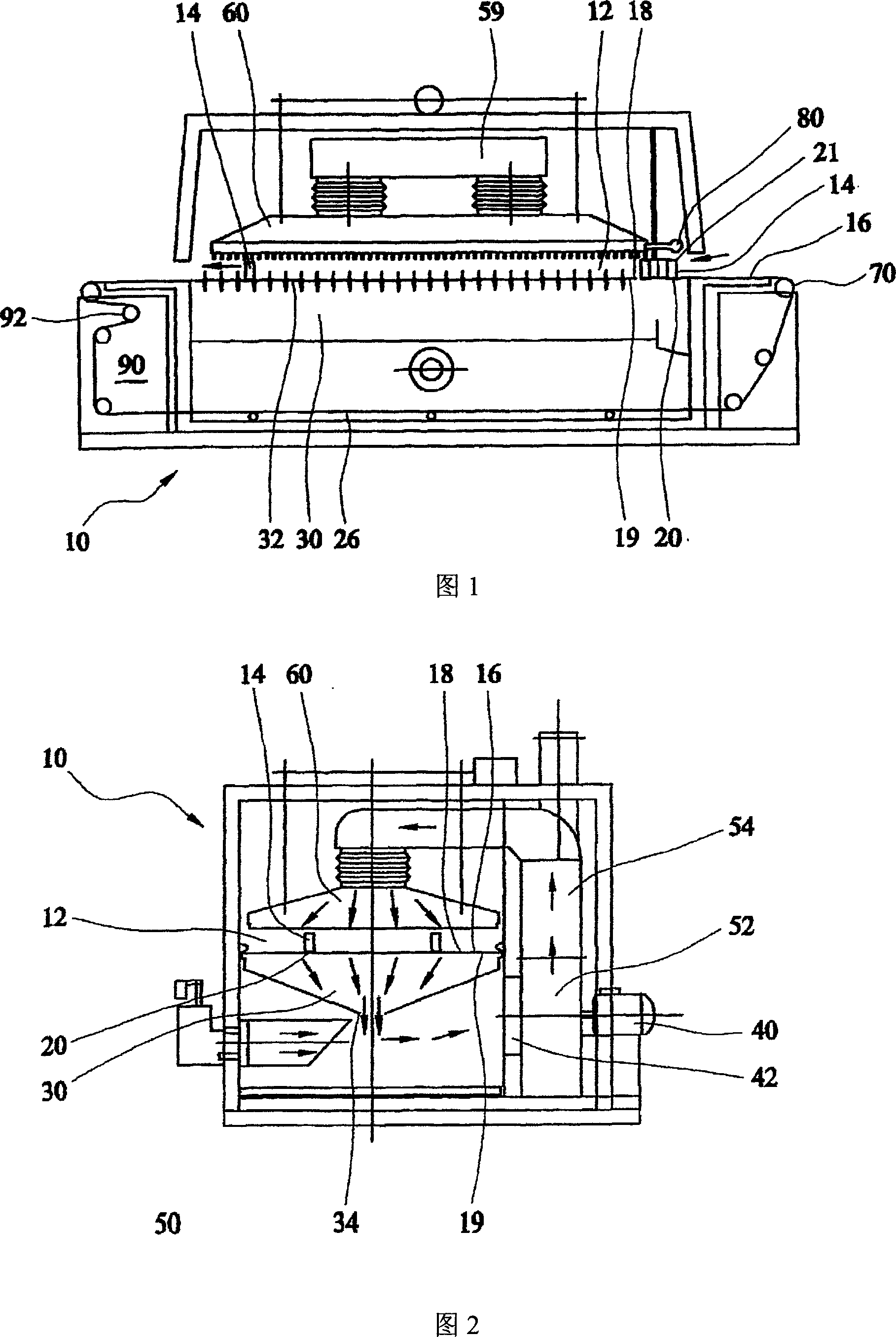
[0039] As shown in FIGS. 1 and 2 , the present invention provides a drying device 10 including a drying chamber 12 . In use, containers, in particular metal beverage containers, preferably cans 14 for drinking, are arranged to pass through the drying device 10 . As mentioned above, the drying equipment 10 is used in the line can making equipment and method, and is arranged after or downstream of the cleaning equipment. Thus, the drying apparatus is used to remove water, chemicals, contaminants and other substances from the tank 14 prior to further processing of the tank 14, such as printing the outside of the tank 14 and coating the inside of the tank 14. moisture.

[0040] The tanks 14 are supported on support means in the form of conveyor belts 16 . The conveyor belt 16 comprises a Kevlar open mesh type belt. Accordingly, the conveyor belt 16 has a plurality (or, more specifically, a large number) of fluid passages through the conveyor belt.

[0041] The cans 14 are arra...


PUM


Abstract

Drying apparatus (10) comprising an oven drying chamber (12) through which container and, in particular, metal beverage container cans (14) are arranged to pass through. The drying apparatus (10) is for use with in-line can producing apparatus and methods and is arranged to locate down-line from washing apparatus. The drying apparatus is arranged to remove water, chemicals, contaminants etc. from the cans prior to the further processing (e.g. printing) of the cans. The cans are supported on a Kevlar open mesh conveyor belt and a suction chamber is created to draw or attract the cans to the conveyor belt to increase the stability of the cans. Accordingly, this greater stability means that the air pressure of the convecting drying air can be greater when compared to prior art unstabilise drying apparatus.

Description

field of invention [0001] The present invention relates to a drying device and a drying method, and in particular but not limited to a metal beverage container drying device and a metal beverage container drying method. Background technique [0002] The canning process converts coiled metal (aluminum or steel) into a complete finished liquid container (ie, a can). This kind of tank is produced or manufactured through a series of assembly line equipment through metal cupping, deep drawing and thinning processes, also known as DWI (Drawn and Wall Ironed, deep drawing and thinning). These "two-piece" cans are commonly supplied to the beer and beverage canning industry. The basic "two piece" can consists of an open top can and an end piece. The open can generally has a hemispherical bottom with a narrowed flange-like upper end. A permanent opening device is attached to the end piece. The end piece is then welded to the can body after the canning process in the beverage produ...

Claims


Application Information

Patent Timeline
Patent Type & Authority Applications(China)
IPC IPC(8): F26B15/18F26B5/12
CPCF26B5/12F26B15/18
Inventor 威廉·道格拉斯·皮尔逊
Owner GREENBANK TECH
Learn More