
Method for simulating a technical installation

A technology of technical equipment and objects, which is applied in the field of simulation of technical equipment to achieve the effect of reducing simulation costs

Inactive Publication Date: 2007-06-13
SIEMENS AG
View PDF2 Cites 3 Cited by
  • Summary
  • Abstract
  • Description
  • Claims
  • Application Information

AI Technical Summary

Problems solved by technology

The disadvantage of this method is the need for a virtual mapping of the overall image of the entire technical plant including all components and connecting lines, as well as the need for large memory and time-consuming simulations

Method used


Image

  • Method for simulating a technical installation
  • Method for simulating a technical installation

Examples


Embodiment Construction

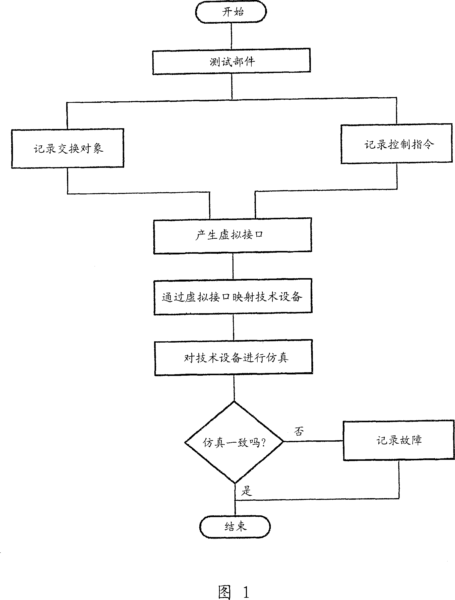
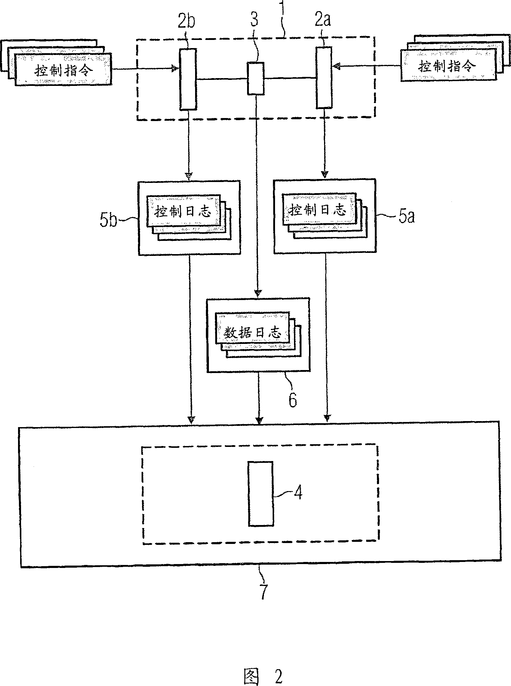
[0018] In this selected example, the flow chart of the method according to the invention shown in FIG. 1 is started on the basis of a test call of a control command selected for at least one component. The data log recorded on the real interface and the control commands in the form of a control log for the components connected to the real interface are used in the simulation environment to generate a virtual interface which is an image of the real interface. The entire technical installation is then converted into a model with the aid of the generated virtual interface. In this case, every two interconnected components can be simulated by means of a virtual interface, or a plurality of interconnected components can be represented by a virtual interface. The image of the technical installation produced in this way is then used to simulate the changed configuration and operating sequence and / or process sequence within the technical installation. During the simulation of the ope...


PUM


Abstract

The invention relates to a method for simulating a technical installation consisting of at least two components connected to one another via a real interface. An exchange of exchange objects ensues between the components via the real interface. The exchange of exchange objects is logged in the form of data logs. The control statements are likewise logged in the form of control logs on the components connected via the real interface. A virtual image of the real interface is generated with the aid of the data logs and control logs, whereby the exchange behavior of the components only implicitly goes into the virtual image. The exchange behavior of the components is subsequently simulated by means of the virtual interface.

Description

technical field [0001] The invention relates to a method for simulating a technical installation consisting of at least two components which are connected to each other via a real interface and between which exchange objects are exchanged, wherein the exchange The exchange of objects between the components on the real interface is recorded in the form of a data log, and in this method the control commands for the components connected via the real interface are also recorded as a control log. The invention also relates to a computer program product comprising the method of the invention. Background technique [0002] A technical device within the meaning of the invention includes any device which on the one hand consists of at least two interconnected parts and on the other hand performs the exchange of exchanged objects via connecting wires between the parts. In this case, the technical device can be an electrical device, a process device or a process technology device. Pr...

Claims


Application Information

Patent Timeline
Patent Type & Authority Applications(China)
IPC IPC(8): G05B19/418G05B19/042G05B17/02
CPCG05B2219/23453G05B2219/23445G05B19/41885G05B17/02G05B19/0428Y02P90/02
Inventor 于尔根·鲍尔雷斯
Owner SIEMENS AG
Learn More