Oppositely clamped type direct-acting valve

A direct-acting valve and clamp-type technology, which is applied in the direction of lifting valve, valve detail, safety valve, etc., can solve the problems of increased manufacturing cost and bulkiness, and achieve the effects of reduced manufacturing cost, overall weight reduction and size reduction

Active Publication Date: 2007-06-20
KANE KOUGYOU
View PDF1 Cites 0 Cited by
  • Summary
  • Abstract
  • Description
  • Claims
  • Application Information

AI Technical Summary

Problems solved by technology

[0006] However, if the valve box is formed with a flange, such as in the case of a flange-type direct acting valve, some problems arise, so that not only the valve itself will become heavy, but also the manufacturing cost of the valve will be high due to the high cost of the flange itself. material cost increases

Method used


Image

  • Oppositely clamped type direct-acting valve
  • Oppositely clamped type direct-acting valve
  • Oppositely clamped type direct-acting valve

Examples


Embodiment Construction

[0019] Next, an example as an embodiment of the present invention will be described based on the drawings.

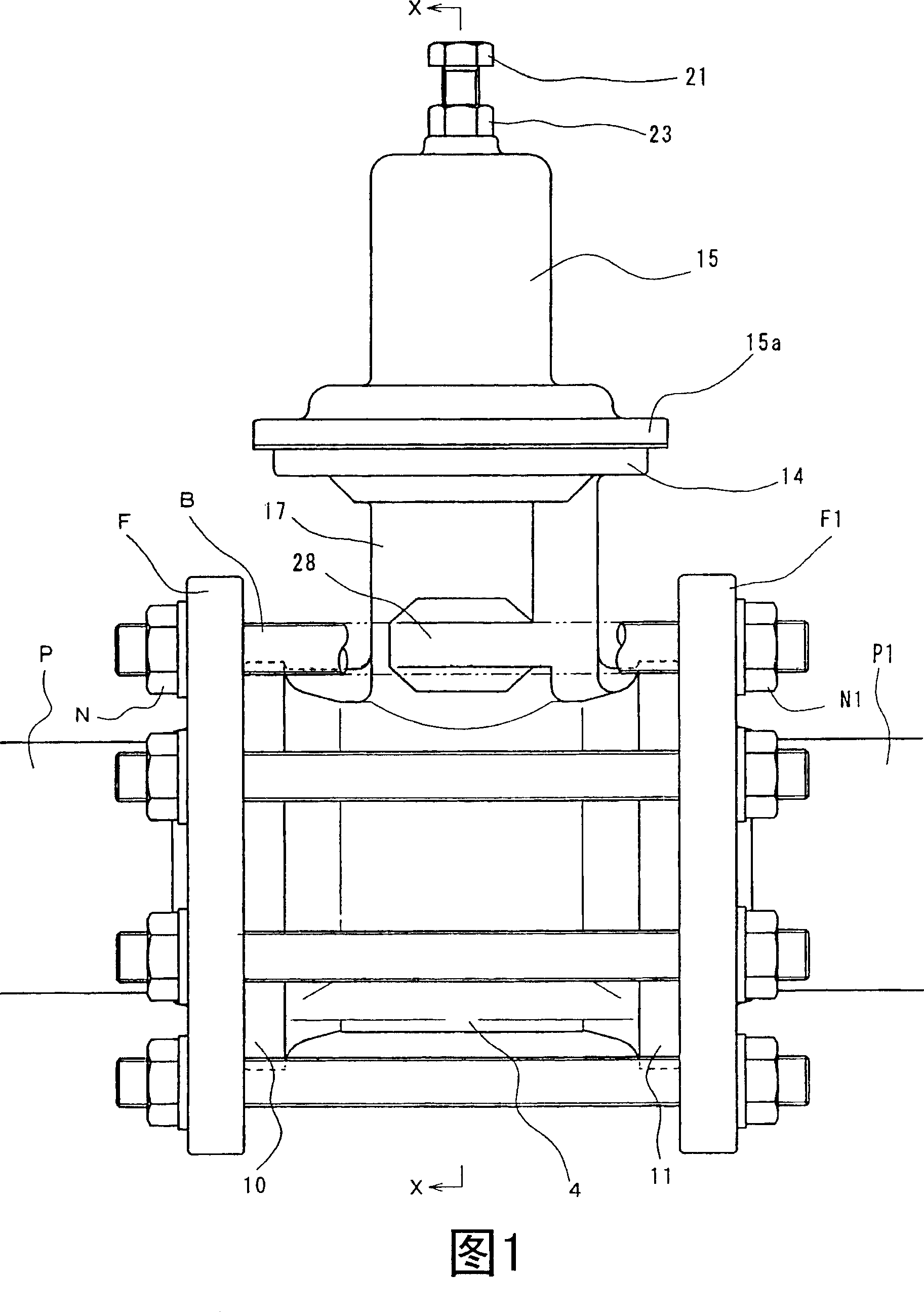
[0020] Fig. 1 is a front view of a piping state of a wafer type direct acting valve.

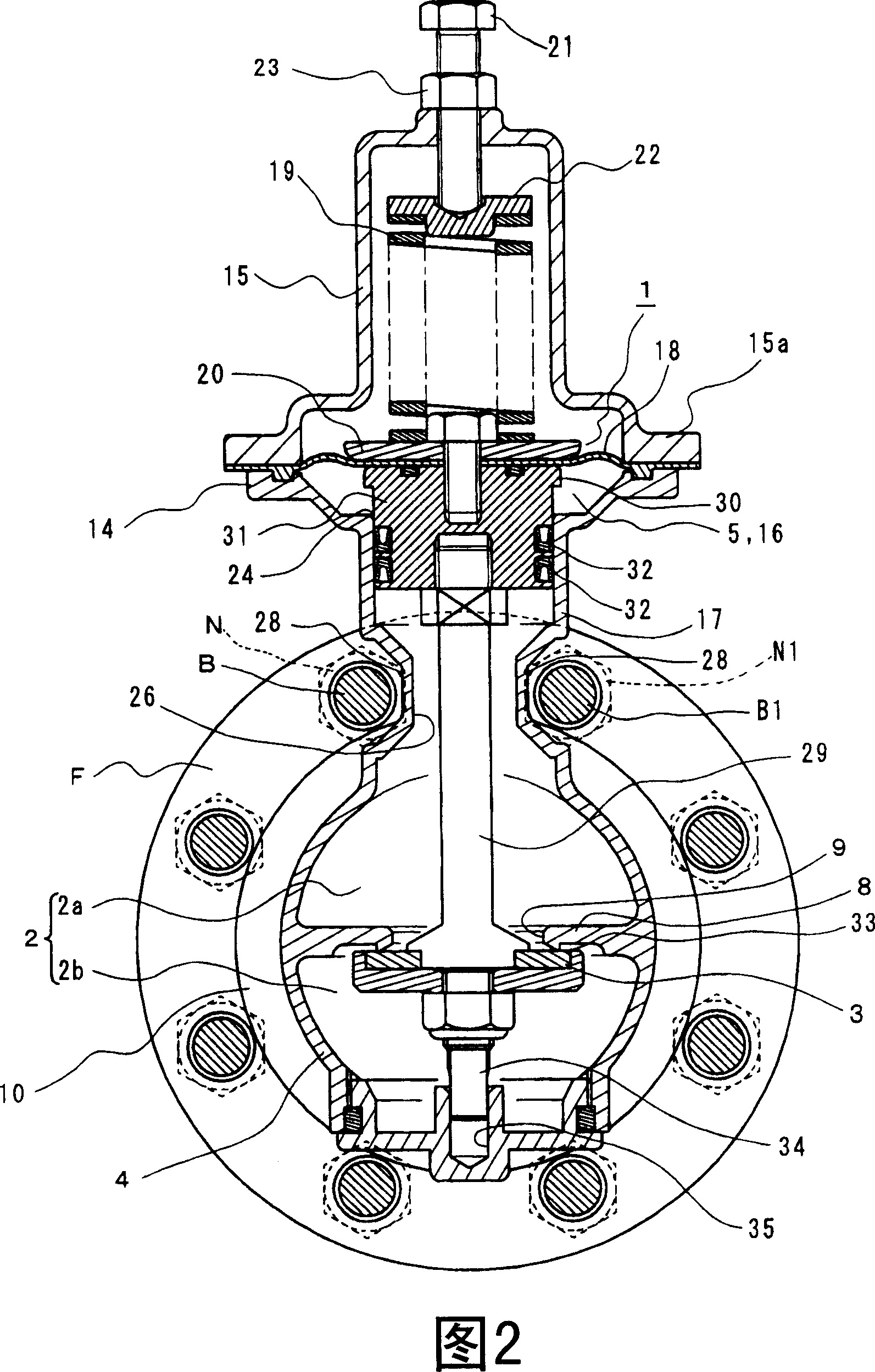
[0021] Fig. 2 is a cross-sectional view taken along line X-X of Fig. 1 .

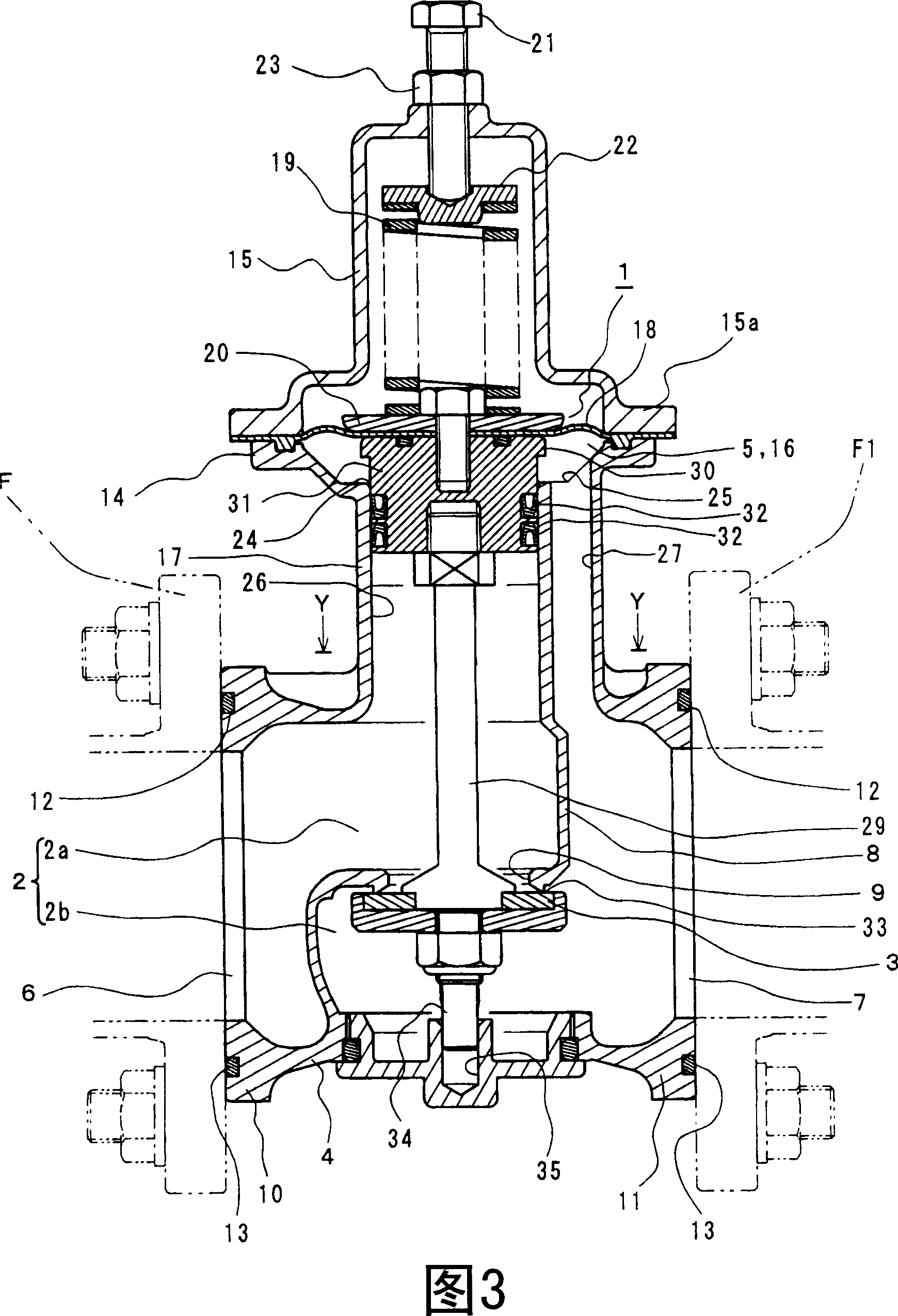
[0022] Fig. 3 is a longitudinal sectional view taken along line X-X in Fig. 1 .

[0023] FIG. 4 is an enlarged cross-sectional view taken along line Y-Y of FIG. 3 with part omitted.

[0024] The valve is a direct-acting valve, which includes a driving part 1 that operates when primary pressure or secondary pressure is detected, and a valve body 3 that communicates with (or is connected to) the driving part 1 and is manipulated to open and close flow path 2. The valve shown is a direct acting pressure reducing valve.

[0025] The structure of the direct acting pressure reducing valve is as follows. The valve box (or valve chamber) 4 includes the flow path 2 (including the primary flow path 2a and the second...


PUM


Abstract

In the direct-acting valve of the present invention, no flange is formed in the valve box and the piping is achieved by interposing the valve box between pipe flanges. The direct-acting valve of the present invention includes: a driving section 1 that operates by sensing a primary pressure or a secondary pressure; and a valve body 3 communicating with the driving section 1 to open and close a flow path 2. A valve box 4 of the valve is sandwiched between pipe flanges F and Fl tightened by bolts B, B1 ... and nuts N, N1 .... Connecting end portions 10 and 11 to be mated with pipe flanges F and F1 that respectively have an inlet and an outlet 6 and 7 of the flow path 2 are made to be flangeless. A cover flange neck 17 is extended upward from the valve box 4 is formed so as to be interposed between the bolts B and B1 which are provided between the pipe flanges F and F1 and adjacent to each other on the circumference of the pipe flanges F and F1.

Description

technical field [0001] The present invention relates to a wafer-type direct-acting valve in which direct-acting valves such as pressure regulating valves (such as pressure reducing valves), solenoid valves, and constant water level valves are clamped between pipe flanges and bolts through the pipe flange and the like. Background technique [0002] Conventionally, there is a wafer type valve in which the valve box is located between pipe flanges, and the pipe flanges are fastened by bolts and nuts. As this type of valve, there are single plate check valves and flangeless butterfly valves. In these valves, a thin disc-shaped valve body oscillates or rotates within a thin cylindrical valve box, opening and closing a flow path through which fluid flows linearly. These valves are relatively simple in structure and operation (for example, see Non-Patent Document 1). [0003] On the other hand, there are also direct acting valves in which the valve body is connected to the drive...

Claims


Application Information

Patent Timeline
Patent Type & Authority Applications(China)
IPC IPC(8): F16K17/02G05D16/06F16K1/00F16K27/00F16K31/122
CPCY10T137/7825Y10T137/7504F16K41/12F16K27/08F16K17/06F16K27/0236
Inventor 落合优山口寿之
Owner KANE KOUGYOU
Why Eureka
Try Eureka