Method and apparatus for adhering driving component

A technology of driving components and attachment, applied in nonlinear optics, instruments, optics, etc., can solve the problem of high cost, achieve the effects of reducing usage, high connection reliability, and reducing costs

Active Publication Date: 2007-06-20
INNOCOM TECH SHENZHEN +1
View PDF0 Cites 6 Cited by
  • Summary
  • Abstract
  • Description
  • Claims
  • Application Information

AI Technical Summary

Problems solved by technology

[0016] In order to solve the problem of high cost of the drive element attachment method in the prior art, it is necessary to provide a cost-reducing drive element attachment method

Method used


Image

  • Method and apparatus for adhering driving component
  • Method and apparatus for adhering driving component
  • Method and apparatus for adhering driving component

Examples


Embodiment Construction

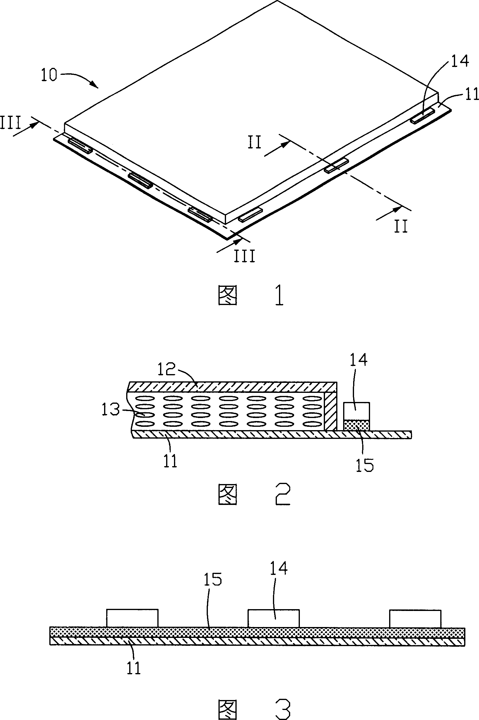
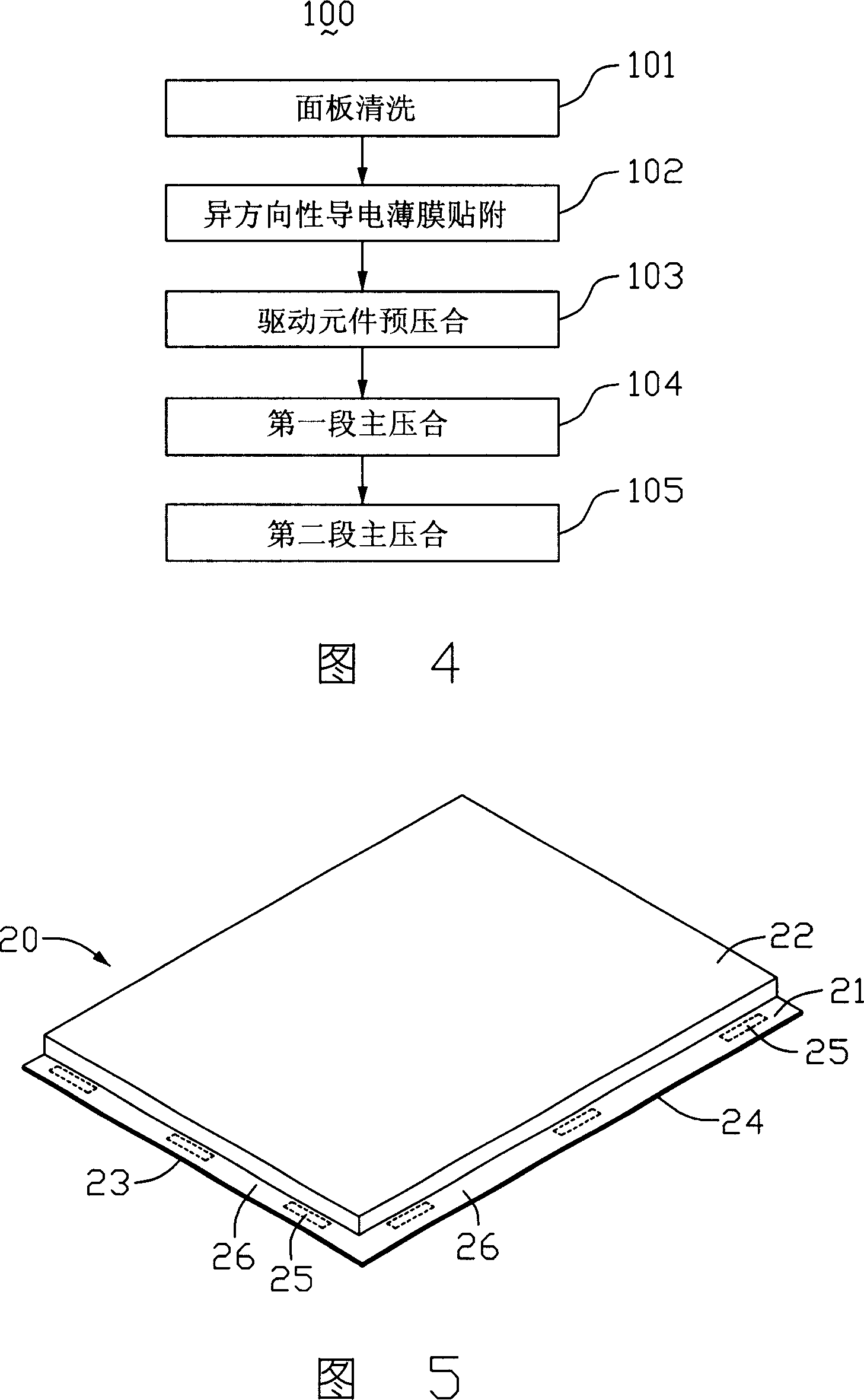
[0039]Please refer to FIG. 5, which is a schematic diagram of the structure of a liquid crystal display panel to which driving elements are to be attached. The liquid crystal display panel 20 includes a first substrate 21, a second substrate 22, and a liquid crystal layer (not shown) sandwiched between the first substrate 21 and the second substrate 22. The first substrate 21 includes a first end 23 and a second end 24 adjacent to each other, and both ends 23 and 24 are provided with attachment areas (not labeled). In the attaching area, the area carrying the driving element is the connecting area 25, and the area between the connecting areas 25 is the spacing area 26.

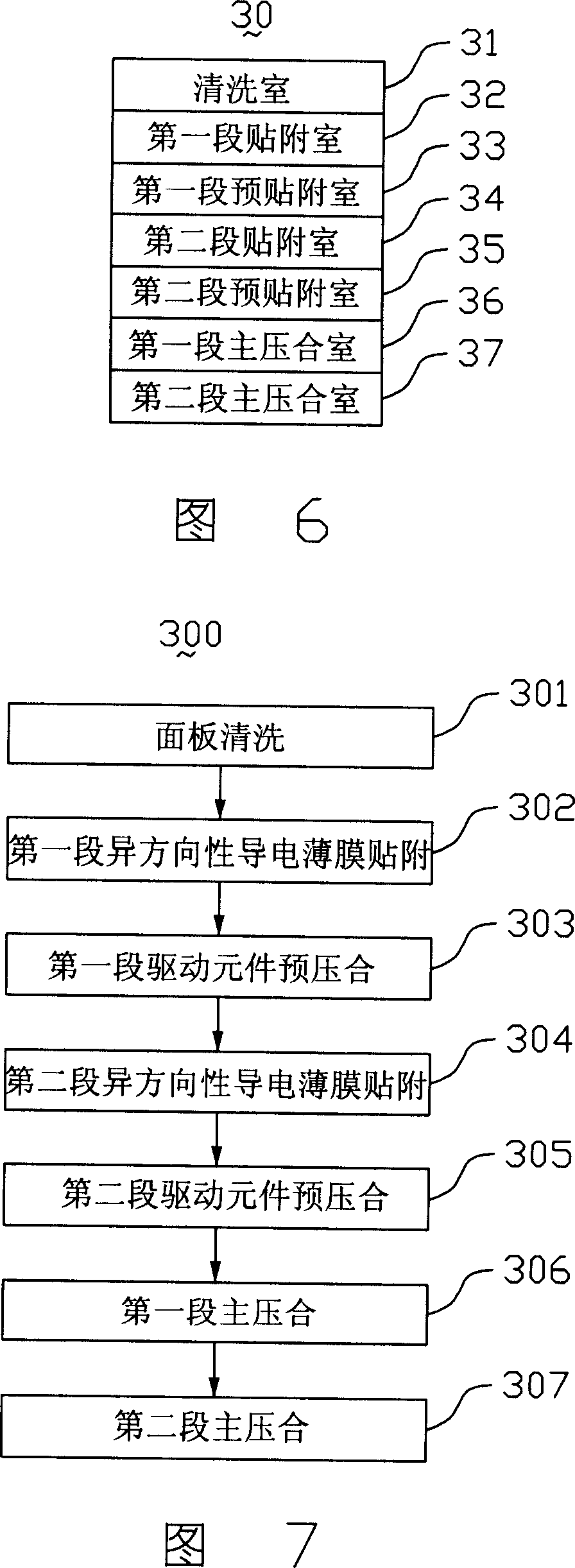
[0040] Please refer to FIG. 6, which is a schematic structural diagram of the first embodiment of the driving element attaching device of the present invention. The driving element attaching device 30 is used to attach the driving element to the liquid crystal display panel 20, which includes a sequentially arrang...


PUM


Abstract

A method for sticking the driving elements includes providing liquid crystal display face plate with base plate having two ends both being set with sticking region (SR) including connection region, cleaning said SR, sticking heteroscedasticity conduction film at the first end SR and the second end SR of said base plate separately, setting a driving element at the first end connection region and the second end connection region separately then pre-pressing these driving elements, carrying out master pressing on said driving elements at two said ends for making them be connected with said base plate.

Description

【Technical Field】 [0001] The present invention relates to a method and equipment for attaching a driving element, and in particular to a method and equipment for attaching a driving element of a liquid crystal display device (Liquid Crystal Display, LCD). 【Background technique】 [0002] Liquid crystal display devices are becoming more widely used due to their low radiation, lightness, thinness, short size, and low power consumption. With the maturity and innovation of related technologies, the types of liquid crystal display devices are also increasing. [0003] A liquid crystal display device adopting an active matrix array generally includes a pixel area formed by a plurality of gate lines and source lines intersecting each other arranged on the same substrate, and a plurality of thin film transistors (Thin Film Transistors) arranged at the intersection of the gate lines and the source lines. Transistor, TFT), wherein each pixel area has a pixel electrode, and the thin film tra...

Claims


Application Information

Patent Timeline
Patent Type & Authority Applications(China)
IPC IPC(8): G02F1/136G02F1/133G09G3/36
Inventor 陈冠欣赖耿民萧志弘王敏政
Owner INNOCOM TECH SHENZHEN
Why Eureka
Try Eureka