

Operating lever system
A technology of operating levers and cam grooves, applied in the field of operating lever systems, which can solve the problems of increased cost and increased number of assembly steps
- Summary
- Abstract
- Description
- Claims
- Application Information
AI Technical Summary
Problems solved by technology
Method used
Image

Examples
no. 1 example
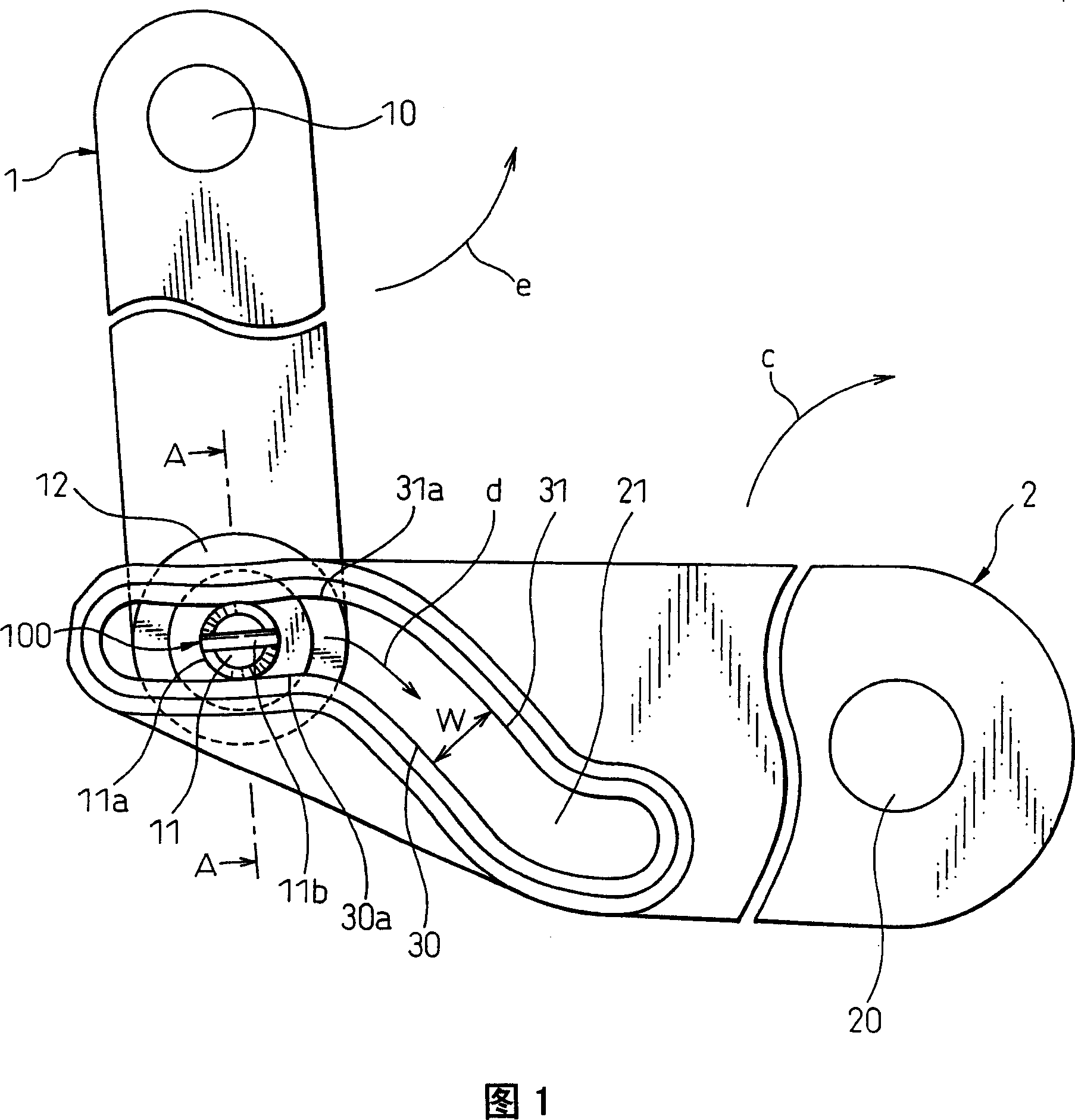
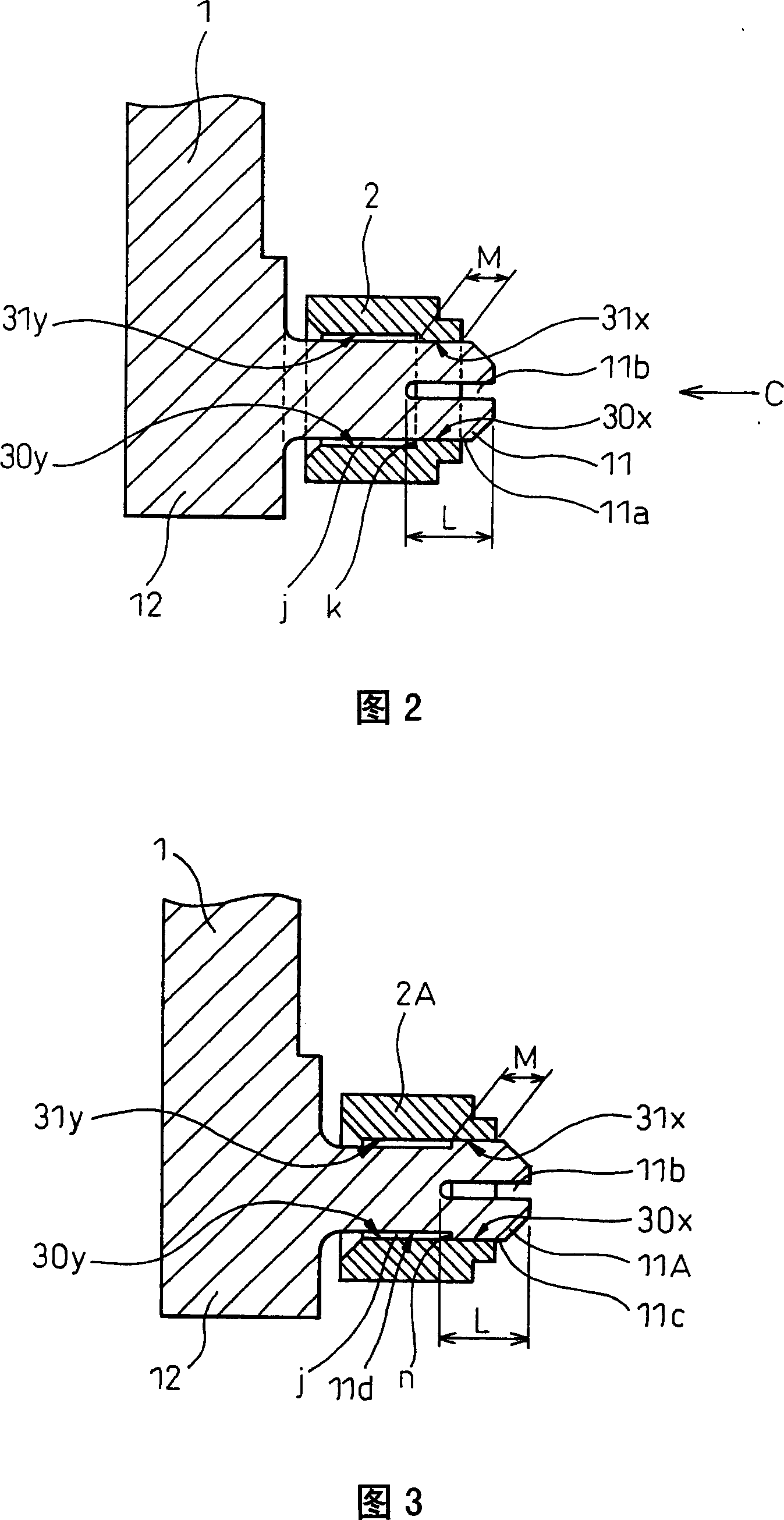
[0025] First, a first embodiment of the present invention will be described. FIG. 1 is a plan view of a first embodiment of the system of the present invention, and FIG. 2 is a cross-sectional view along line AA of FIG. 1 . The first embodiment of the present invention comprises a drive rod 1 and a driven rod 2 made of a plastic having superior mechanical strength and wear resistance, such as polyacetal or polypropylene.
[0026] The driving rod 1 is formed at one end with a shaft hole 10 into which a shaft of an unshown servo motor is inserted, and at the same time, the driving rod 1 is driven by the servo motor and rotates around the shaft hole 10 . In FIG. 1 , the other end of the drive rod 1 is formed with a base 12 provided with a cylindrical pin 11 at the bottom.
[0027] The follower lever 2 is rotatable about a fulcrum 20 at one end. In FIG. 1 , the cam groove 21 is formed from the left side toward the fulcrum side. Also, the pin 11 of the drive lever 1 is slidably ...
no. 2 example
[0036] Next, a second embodiment of the present invention will be described based on FIG. 3 . FIG. 3 is a view corresponding to FIG. 2 of a second embodiment of the present invention. The same reference numerals as in the first embodiment denote elements having the same functions as in the first embodiment, and explanations are omitted. In the first embodiment, the shaft diameter of the pin 11 is the same, and the side wall of the cam groove has a two-step shape, one of which is used as a sliding surface, but it is also possible to eliminate the step difference of the side wall of the cam groove and make The outer diameter of the shaft of the pin is a two-step shape, and the first step is used as a sliding surface against the side wall of the cam groove.
[0037] That is, as shown in FIG. 3, let the outer circumference (shaft outer circumference) of the pin shaft 11A be a two-step shape constituted by the outer circumference 11c and the outer circumference 11d, wherein the ou...
no. 3 example
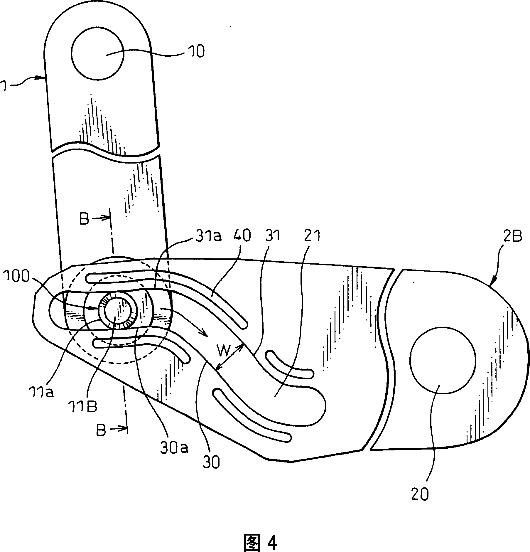
[0039] Next, a third embodiment of the present invention will be described with reference to FIGS. 4 and 5 . Fig. 4 is a plan view showing a third embodiment of the present invention. Fig. 5 is a sectional view along line B-B of Fig. 4 . The same reference numerals as in the first embodiment denote elements having the same functions as in the first embodiment, and explanations are omitted.
[0040] In the first embodiment described above, the pin 11 is provided with the slit 11b. The slit 11b has flexibility at the sliding portion of the front end of the pin, so when the pin slides, the frictional resistance between the pin and the cam groove is reduced. On the other hand, in the third embodiment, the pin is not provided with any slit. The elastic deformation groove is provided near the cam groove of the second lever, whereby the side walls 30, 31 of the cam groove on the opposite sides are given flexibility.
[0041] As shown in FIG. 4 , the second rod 2B has a plurality ...
PUM
 Abstract
Description
Claims
Application Information