
Design method for blade of claw rotor

A design method and rotor technology, applied in mechanical equipment, rotary piston pumps, rotary piston machines, etc., can solve problems such as unsmooth operation, reduced service life, noise and vibration, etc.

Active Publication Date: 2007-06-27
GPOUER
View PDF8 Cites 6 Cited by
  • Summary
  • Abstract
  • Description
  • Claims
  • Application Information

AI Technical Summary

Problems solved by technology

The structure of these known claw rotors generally adopts the meshing type of two blades, and its common disadvantage is that the curves of the two blades form a discontinuity at the tip. In terms of mechanical movement, the definition of the working chamber between the rotor, the conjugate rotor and the cavity wall, the expansion and compression process generated by the meshing rotation of the two rotors, when applied to the machinery that needs to perform periodic compression movements of intake and exhaust, This definition defines the process of the working chamber between the rotor and the conjugate rotor and the cavity wall from ineffective compression to expansion of intake air, the two claws will not operate smoothly at the tip, and there will be noise and vibration.
In short, the curve of the blades of the claw rotor is not smooth, which will cause the two blades to mesh poorly with each other, and cause noise and vibration during the expansion and compression process, or cause friction due to improper meshing, which will reduce the use. life

Method used


Image

  • Design method for blade of claw rotor
  • Design method for blade of claw rotor
  • Design method for blade of claw rotor

Examples


Embodiment Construction

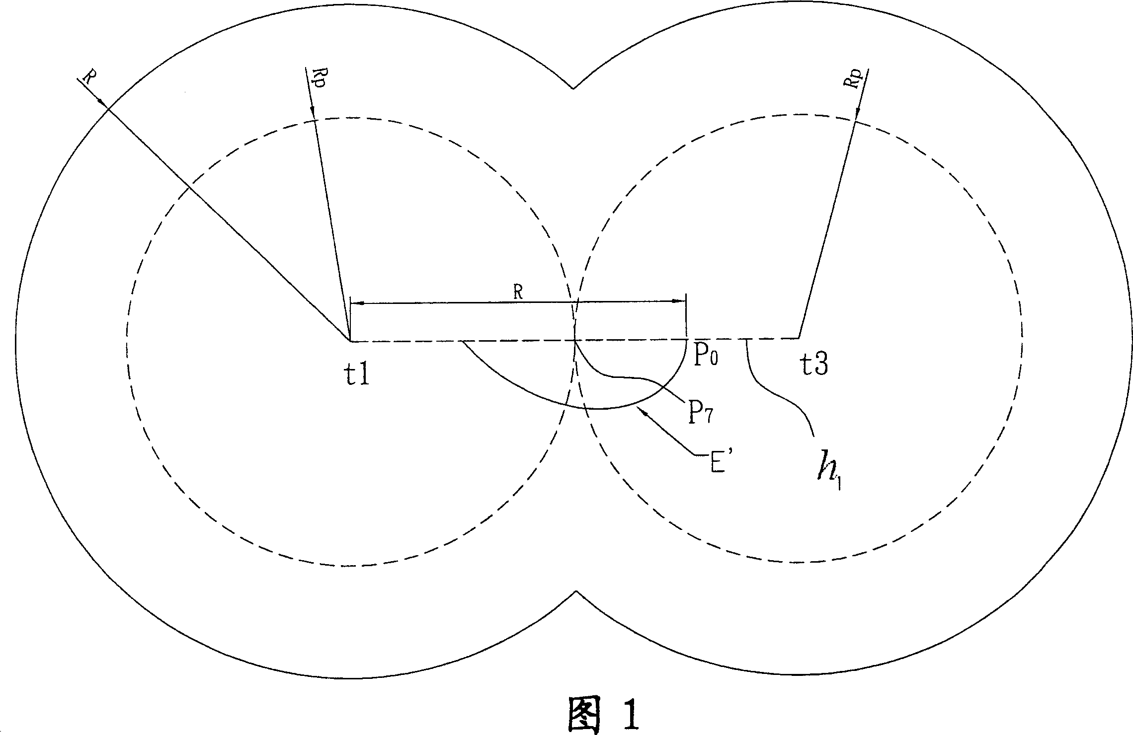
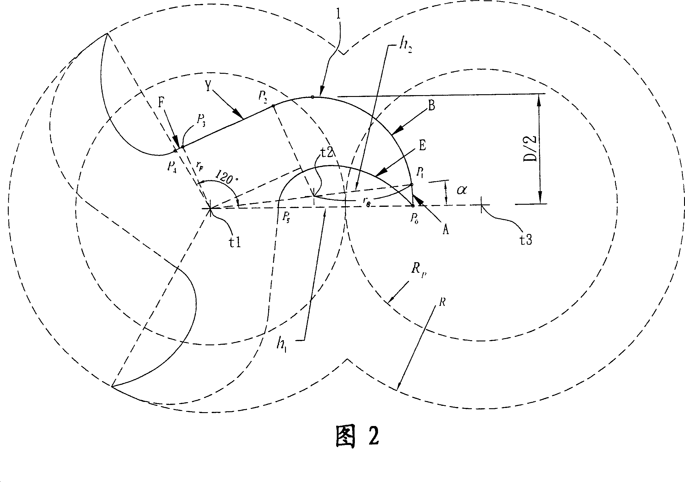
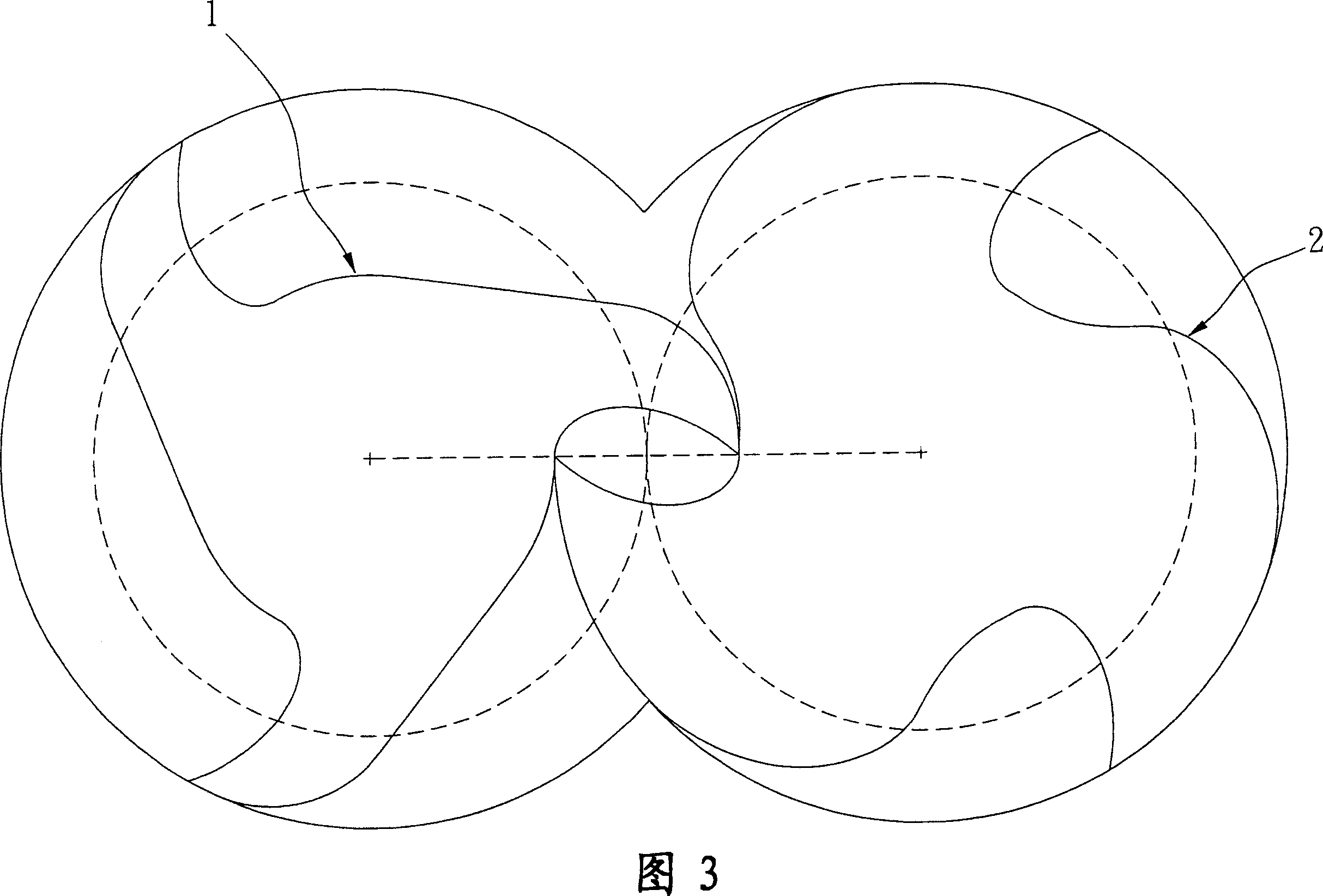
[0031] Please refer to Fig. 1 to Fig. 3, the method for obtaining the three-blade definition rotor 1 and the conjugate rotor 2 of the present invention, as shown in the figure, the three-blade shape acquisition of the definition rotor 1 includes the following steps:

[0032] 1. Specify the maximum radius of the defined rotor R = 60mm, define the rotor width D = 65mm, define the pitch circle radius Rp of the rotor and the conjugate rotor Rp = 40mm, the centers of the two pitch circles are t1 and t3 respectively, Rp is less than R, and define The ratio of the maximum rotor radius R to the pitch circle radius Rp is R=3Rp / 2.

[0033] 2. Please refer to Figure 1, take the center t1 of a pitch circle as the center of the defined rotor, pass through a horizontal line h1, and obtain a first point P on the horizontal line h1 0 , this point P 0 The horizontal distance from the center of the circle t1 is R, from this point P 0 Generate a conjugate curve E' around the pitch circle cente...


PUM


Abstract

A design method for the blade of jaw-type rotor is disclosed. The mutually engaged definite rotor and conjugate rotor with three or more blades are designed by a parameterization method. The profile curve of a single blade for said definite rotor is composed of a curve, three arcs and a straight line. Said definite rotor is obtained through copying said profile curve by N-1 copies, where N is greater than or equal to 3 and sequentially turning them by 360 / N-(N-1) 360 / N deg. Said jaw-type rotor is suitable for the periodical expansion-compression machine.

Description

technical field [0001] The present invention relates to a blade design method of a claw rotor, which is an additional patent application of China Taiwan Invention Patent Application No. 94124780 (U.S. Invention Patent Application No. 11 / 214,876). The method can obtain three blades or The definition of the rotor and the conjugate rotor with more than three blades that are conjugated to each other, and evaluate the performance of the rotor with the best conjugated mesh to provide a higher compression ratio and delivery volume, without noise and vibration, and with better fit The meshing effect to reduce leakage. Background technique [0002] It is known that claw rotors can be divided into single-blade, double-blade, and three-blade structures. A defined rotor and a conjugate rotor (a conjugate rotor) with the same type of blades mesh with each other, and the blades are meshed and rotated to provide For machines that need to perform periodic cyclical motions of expansion and ...

Claims


Application Information

Patent Timeline
Patent Type & Authority Applications(China)
IPC IPC(8): F01C1/18F04C18/18
Inventor 钟添东林恒毅
Owner GPOUER
Learn More