
Method and magnetic resonance system for adjustment of the field strength of RF pulses

A high-frequency pulse and measurement system technology, applied in magnetic resonance measurement, magnetic performance measurement, measurement devices, etc., can solve problems such as high sensitivity

Inactive Publication Date: 2007-06-27
SIEMENS HEALTHCARE GMBH
View PDF0 Cites 14 Cited by
  • Summary
  • Abstract
  • Description
  • Claims
  • Application Information

AI Technical Summary

Problems solved by technology

[0020] A disadvantage of this method, however, is the long measurement time caused by the necessary sequence of N phase-encoding steps compared to the previously described integration method, where N denotes the matrix size in the phase-encoding direction
Another disadvantage is the higher sensitivity to movement of the examination object (ie the human body) during the examination

Method used


Image

  • Method and magnetic resonance system for adjustment of the field strength of RF pulses
  • Method and magnetic resonance system for adjustment of the field strength of RF pulses
  • Method and magnetic resonance system for adjustment of the field strength of RF pulses

Examples


Embodiment Construction

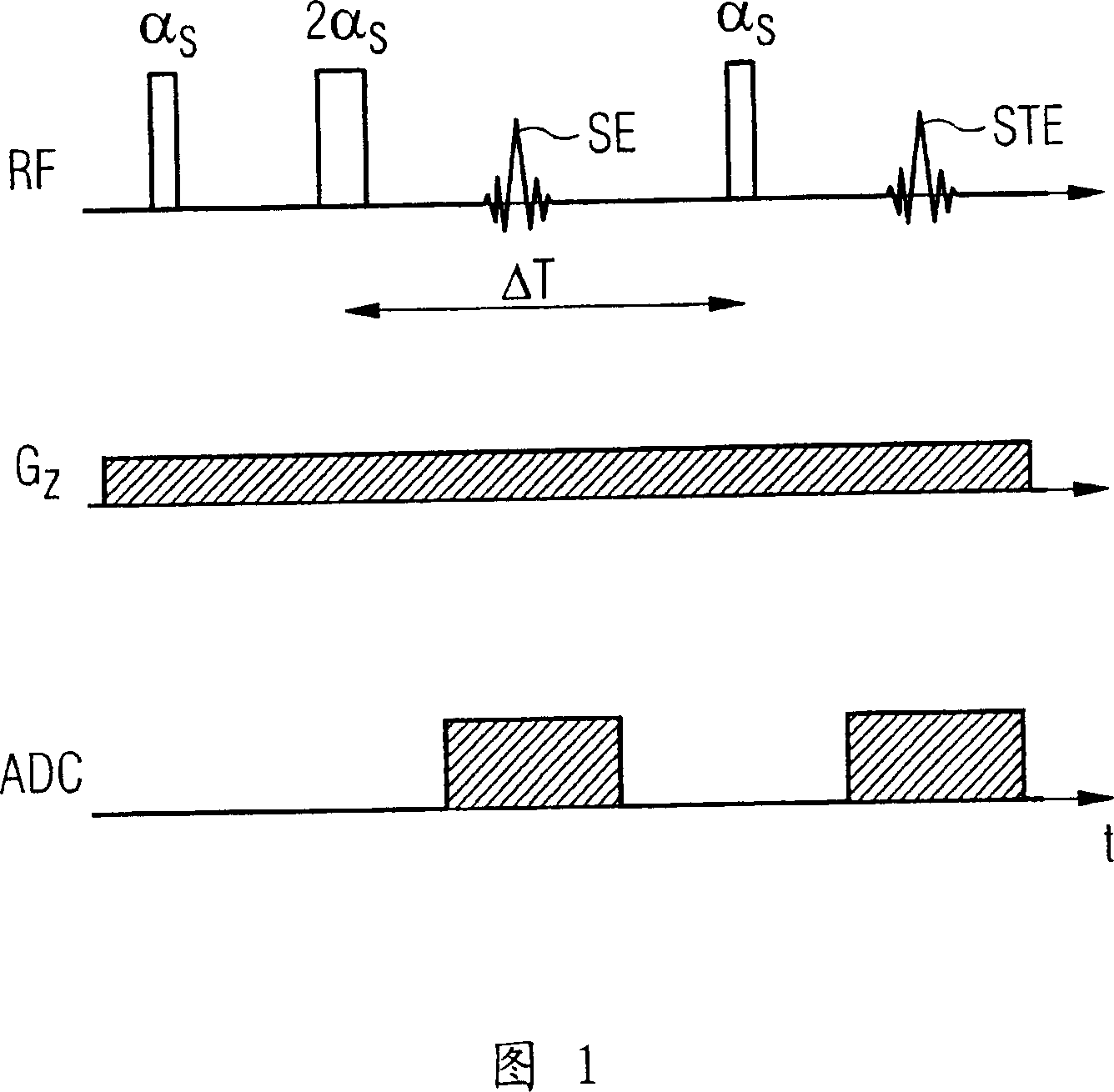
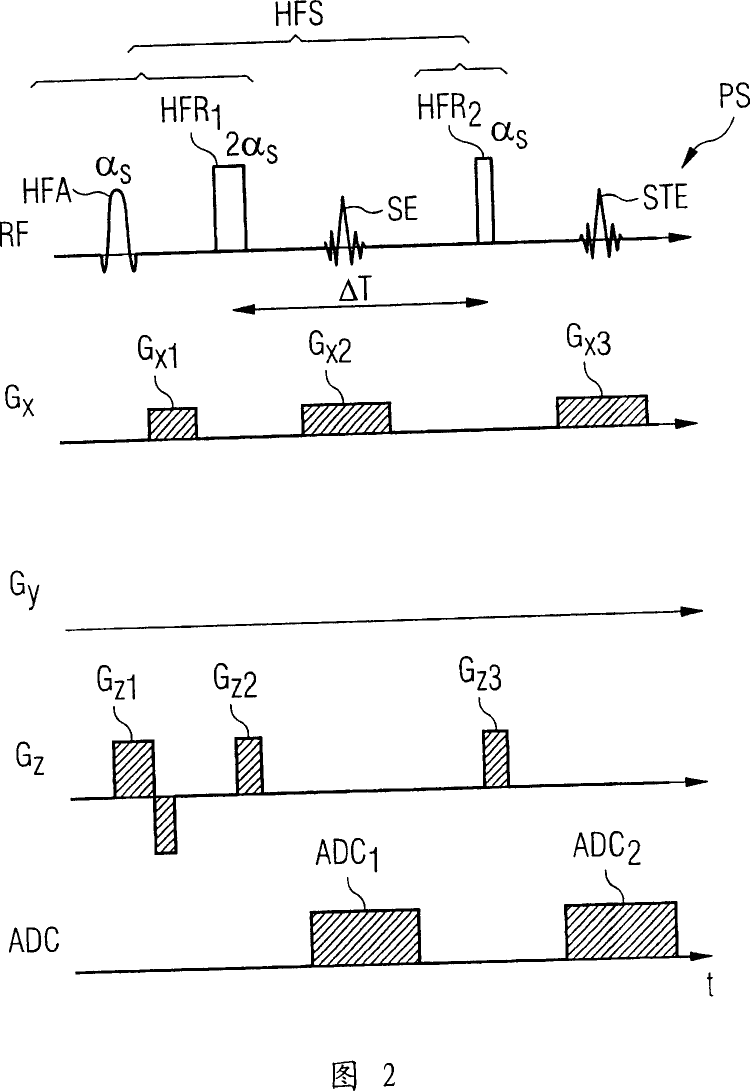
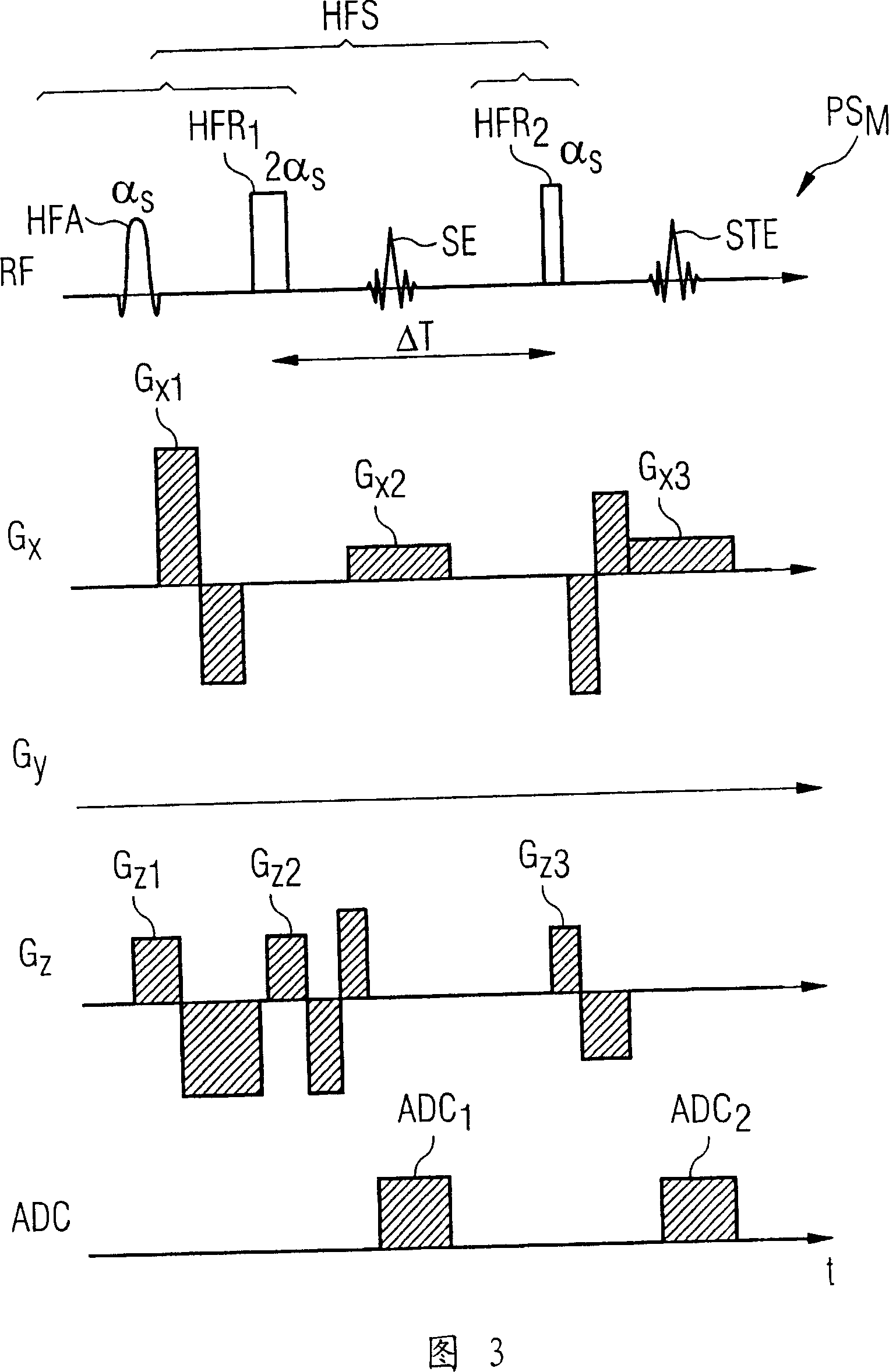
[0054] In the pulse pattern shown in FIG. 1 , the pulses emitted by the radio-frequency transmitting antenna are shown in the usual manner on a parallel time axis (i.e. at time t) and in terms of the time relative to the radio-frequency pulse The dependencies on are matched to switch on the gradient.

[0055] In this case, the pattern shown in FIG. 1 refers to a common pattern already explained at the beginning of the text for conventionally determining the average flip angle in a slice volume. On the uppermost axis labeled RF (radio frequency) the high frequency pulses emitted by the high frequency transmitting antenna are plotted. The gradient G shown below it z is the so-called slice-selective gradient or slice-selective gradient, which is generally applied in the z direction, ie in the direction of the basic magnetic field, and serves to select a specific layer or a specific partial volume during spin excitation. The time window in which the signal is measured by means o...


PUM


Abstract

In a method for adjustment of the field strength of radio-frequency pulses as well as a magnetic resonance measurement system, radio-frequency pulses are emitted by a radio-frequency antenna of a magnetic resonance measurement system in a magnetic resonance measurement A test volume slice is initially excited by emission of radio-frequency pulses with a defined pulse amplitude by the appertaining radio-frequency antenna and one-dimensional, spatially-resolved characteristic values are determined along an extent direction of the test volume slice. The one-dimensional, spatially-resolved characteristic values respectively represent a local field strength of the B1 field in strips of the test volume slice running perpendicular to the extent direction. An average value of the determined characteristic values is then formed over at least over one determined segment along the extent direction of the test volume slice. A pulse amplitude of the radio-frequency pulses that is to be set for the magnetic resonance measurement to be implemented is determined on the basis of the average value.

Description

technical field [0001] The invention relates to a method for adjusting the field strength of radio-frequency pulses emitted by a radio-frequency antenna of a magnetic resonance measurement system during a magnetic resonance measurement. Furthermore, the invention relates to a magnetic resonance measurement system comprising a radio-frequency antenna and a corresponding adjustment device for adjusting the field strength of radio-frequency pulses emitted by the radio-frequency antenna during a magnetic resonance measurement. Background technique [0002] Magnetic resonance tomography (MR tomography), also known as nuclear spin tomography, refers to a technique that has spread widely during this period for acquiring images inside the body of a living examination subject. In order to obtain an image using this method, the body or the body part to be examined must first be placed in a static state that is as uniform as possible produced by the basic field magnet of the magnetic r...

Claims


Application Information

Patent Timeline
Patent Type & Authority Applications(China)
IPC IPC(8): G01R33/20G01R33/32A61B5/055
CPCG01R33/583G01R33/586
Inventor 索尔斯坦·费威尔彼得·休贝斯索尔斯坦·斯佩克纳
Owner SIEMENS HEALTHCARE GMBH
Learn More