Liquid crystal panel

A liquid crystal panel and liquid crystal layer technology, applied in the direction of transistors, optics, instruments, etc., can solve problems such as poor display effect of liquid crystal panels, achieve good display effect, prevent incision phenomenon, poor contact or disconnection, and effectively connect

Inactive Publication Date: 2007-06-27
INNOCOM TECH SHENZHEN +1
View PDF0 Cites 0 Cited by
  • Summary
  • Abstract
  • Description
  • Claims
  • Application Information

AI Technical Summary

Problems solved by technology

[0010] In order to solve the problem of poor display effect of liquid crystal panels in the prior art, it is necessary to provide a liquid crystal panel with good display effect

Method used


Image

  • Liquid crystal panel
  • Liquid crystal panel
  • Liquid crystal panel

Examples


Embodiment Construction

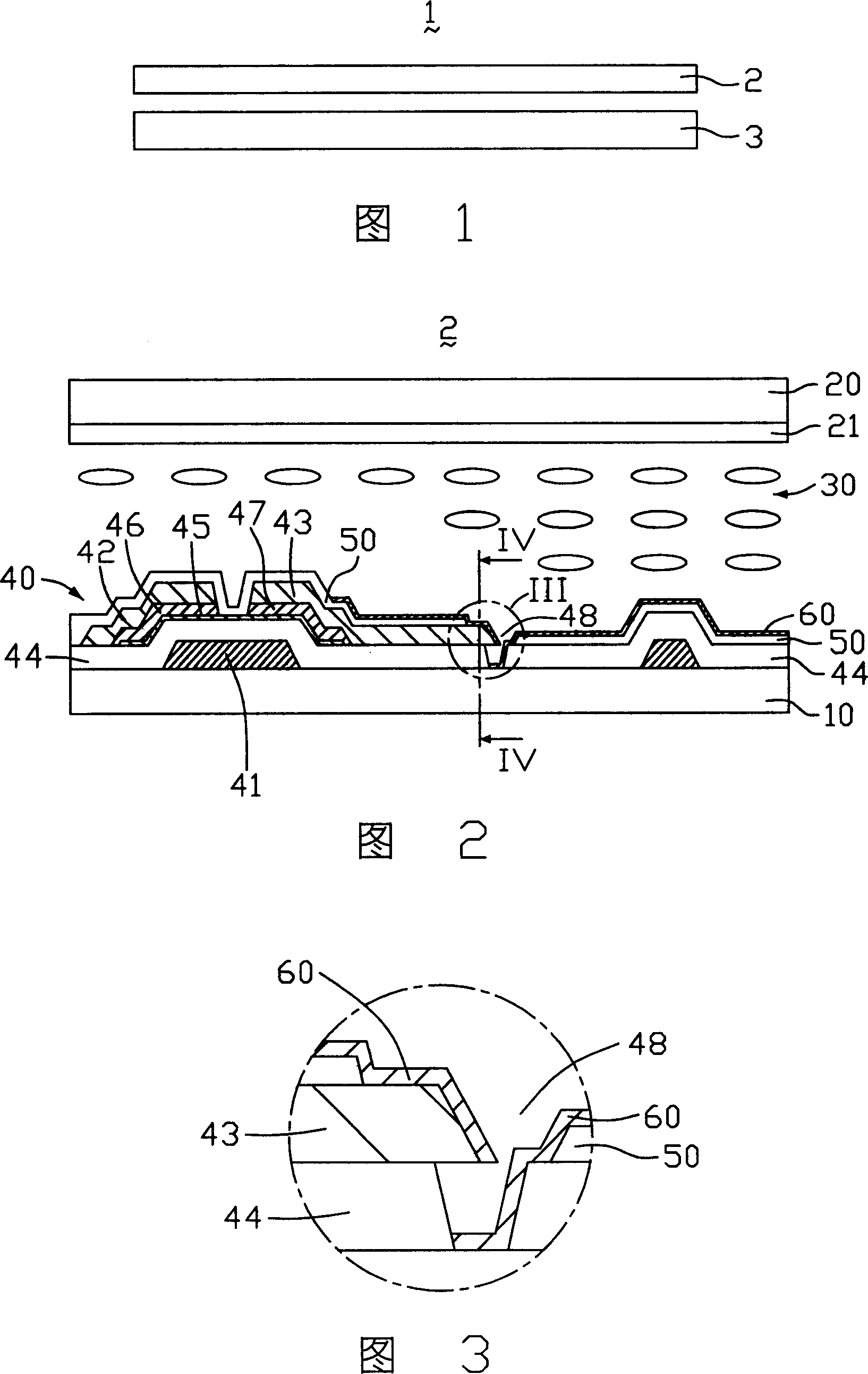
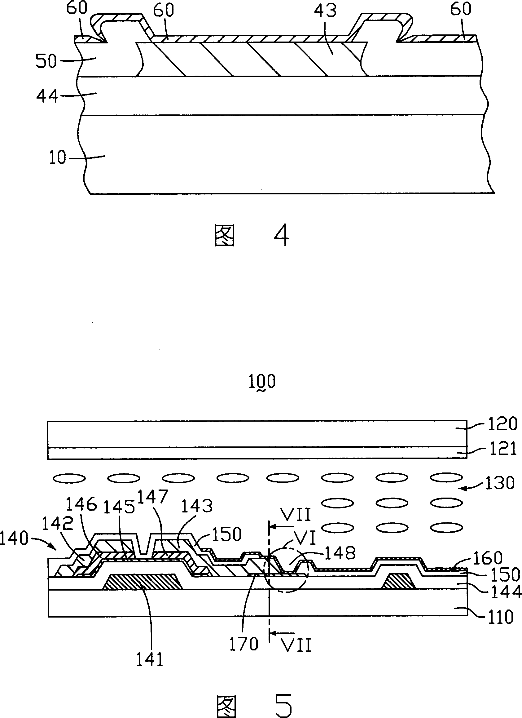
[0020] Please refer to FIG. 5 , which is a schematic structural diagram of the liquid crystal panel of the present invention. The liquid crystal panel 100 includes: a first substrate 110 and a second substrate 120 oppositely disposed, and a liquid crystal layer 130 disposed between the two substrates 110 , 120 . A thin film transistor 140 , a passivation layer 150 and a pixel electrode 160 are disposed on a side of the first substrate 110 close to the liquid crystal layer 130 , and a common electrode 121 is disposed between the second substrate 120 and the liquid crystal layer 130 .

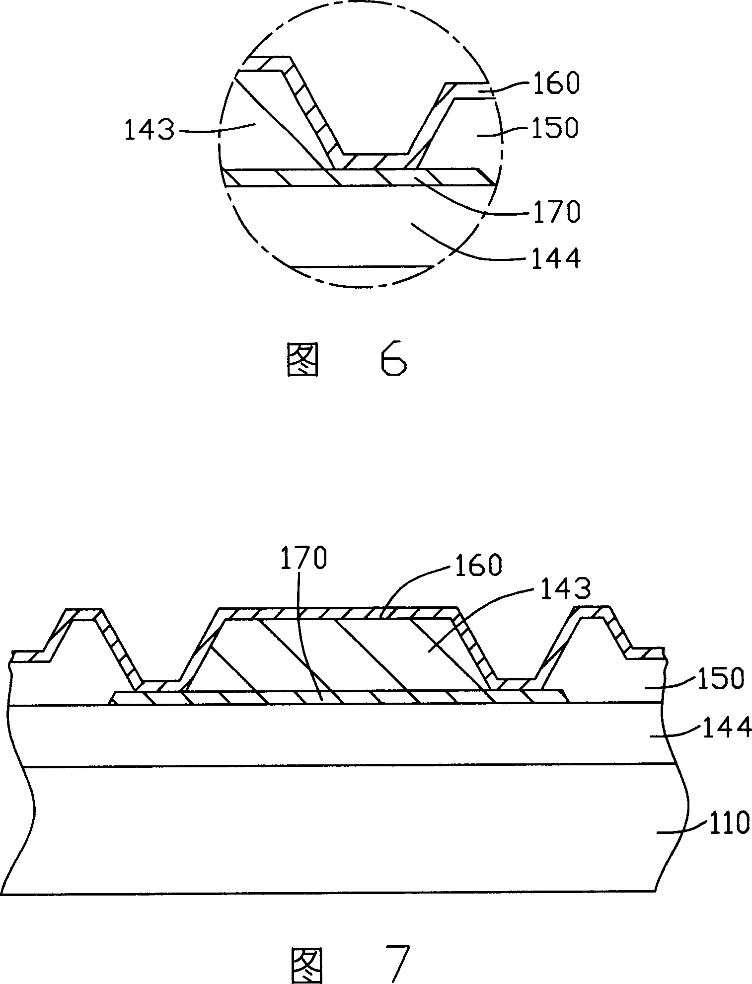
[0021] The TFT 140 includes a gate 141 , a source 142 , a drain 143 and an active layer 145 . The gate 141 is disposed on the first substrate 110, a gate insulating layer 144 is disposed on the gate 141 and the first substrate 110; the active layer 145 is disposed on the gate insulating layer 144 corresponding to the gate 141 and an isolation layer 170 is arranged on the gate insulating layer 14...


PUM


Abstract

The liquid crystal faceplate includes a first base plate, a second base plate, a liquid crystal layer, a thin film transistor (TFT), an isolation layer, a passivation layer, and a pixel electrode. Two base plates are setup oppositely. The liquid crystal layer is located between the two base plates. Being setup on the first base plate, TFT includes grid electrode, source electrode, and drain electrode. The isolation layer is setup corresponding to the drain electrode. Being setup on TFT, the passivation layer includes a contact hole corresponding to the isolation layer. Being setup on the passivation layer, the pixel electrode through the contact hole is connected to the drain electrode electrically.

Description

【Technical field】 [0001] The present invention relates to a liquid crystal panel, in particular to a liquid crystal panel used for a liquid crystal display (Liquid Crystal Display, LCD). 【Background technique】 [0002] Liquid crystal display devices have the advantages of lightness, thinness, and low power consumption, and are widely used in modern information equipment. [0003] Liquid crystal display devices are mainly classified into active matrix liquid crystal display devices and passive matrix liquid crystal display devices according to their driving methods. Passive matrix liquid crystal display devices are the main type of early liquid crystal display devices, and are still widely used in lower-priced products. This type of liquid crystal display device is relatively limited in terms of brightness and viewing angle, and its response speed is relatively slow. However, due to low cost, some displays on the market still use passive matrix liquid crystal display devices...

Claims


Application Information

Patent Timeline
Patent Type & Authority Applications(China)
IPC IPC(8): G02F1/136G02F1/133H01L29/786
Inventor 傅健忠
Owner INNOCOM TECH SHENZHEN
Why Eureka
Try Eureka