Piston pump with improved pressure build-up dynamics

A technology of piston pumps and pistons, which is applied to parts, pumps, brakes, etc. of pumping devices used for elastic fluids, can solve problems such as assembly costs, achieve fewer components, reduce manufacturing and assembly costs, and reduce flow resistance Effect

Inactive Publication Date: 2007-06-27
ROBERT BOSCH GMBH
View PDF0 Cites 5 Cited by
  • Summary
  • Abstract
  • Description
  • Claims
  • Application Information

AI Technical Summary

Problems solved by technology

The valve of this known piston pump therefore has a relatively large number of components, which results in a certain assembly effort
In addition this known piston pump has a certain axial length

Method used


Image

  • Piston pump with improved pressure build-up dynamics
  • Piston pump with improved pressure build-up dynamics
  • Piston pump with improved pressure build-up dynamics

Examples


Embodiment Construction

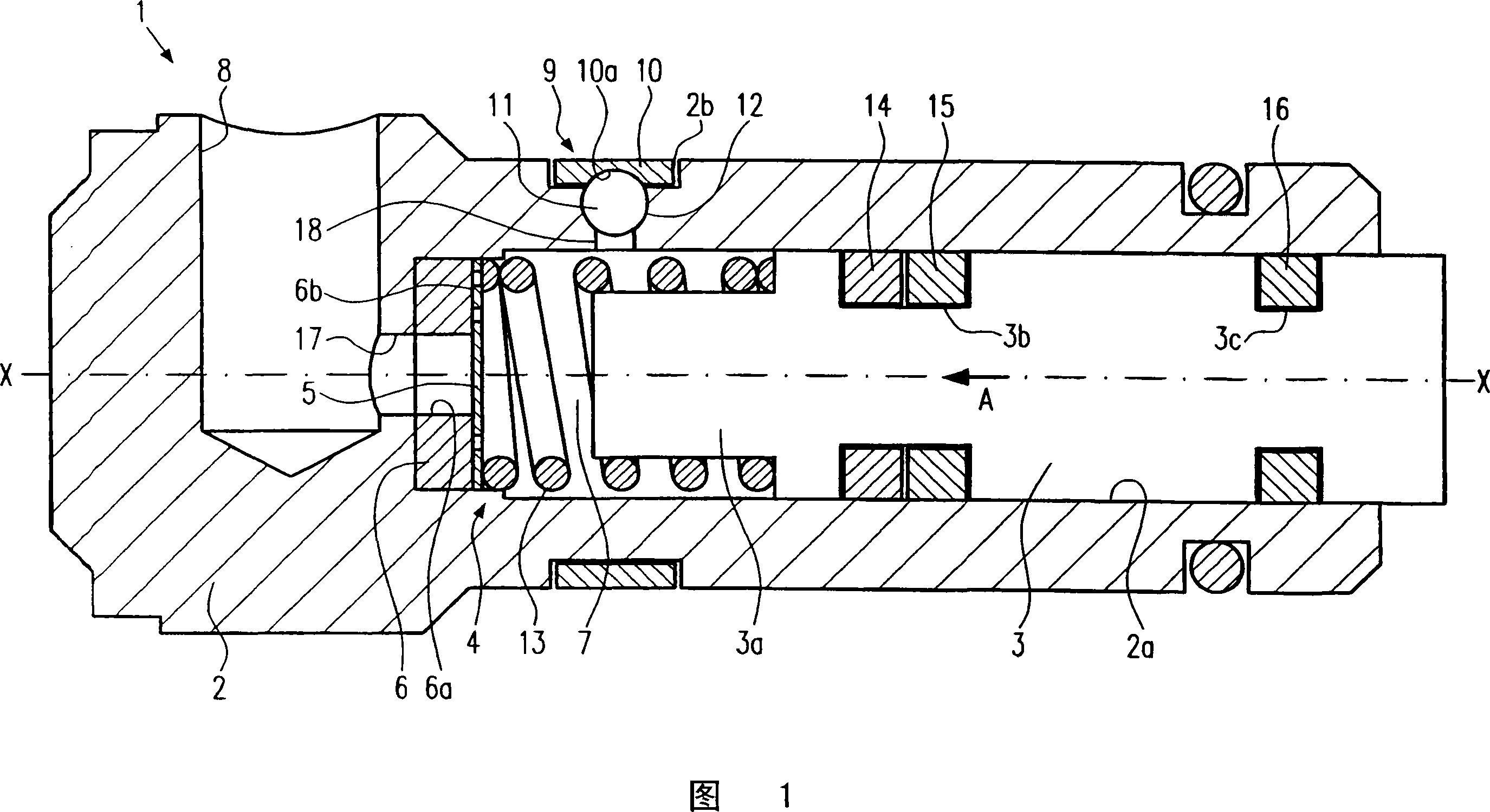
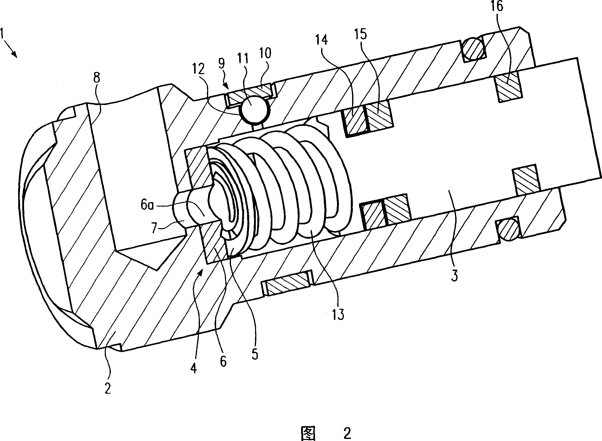
[0027] A piston pump 1 according to a preferred exemplary embodiment of the invention will be described below with reference to FIGS. 1 to 5 .

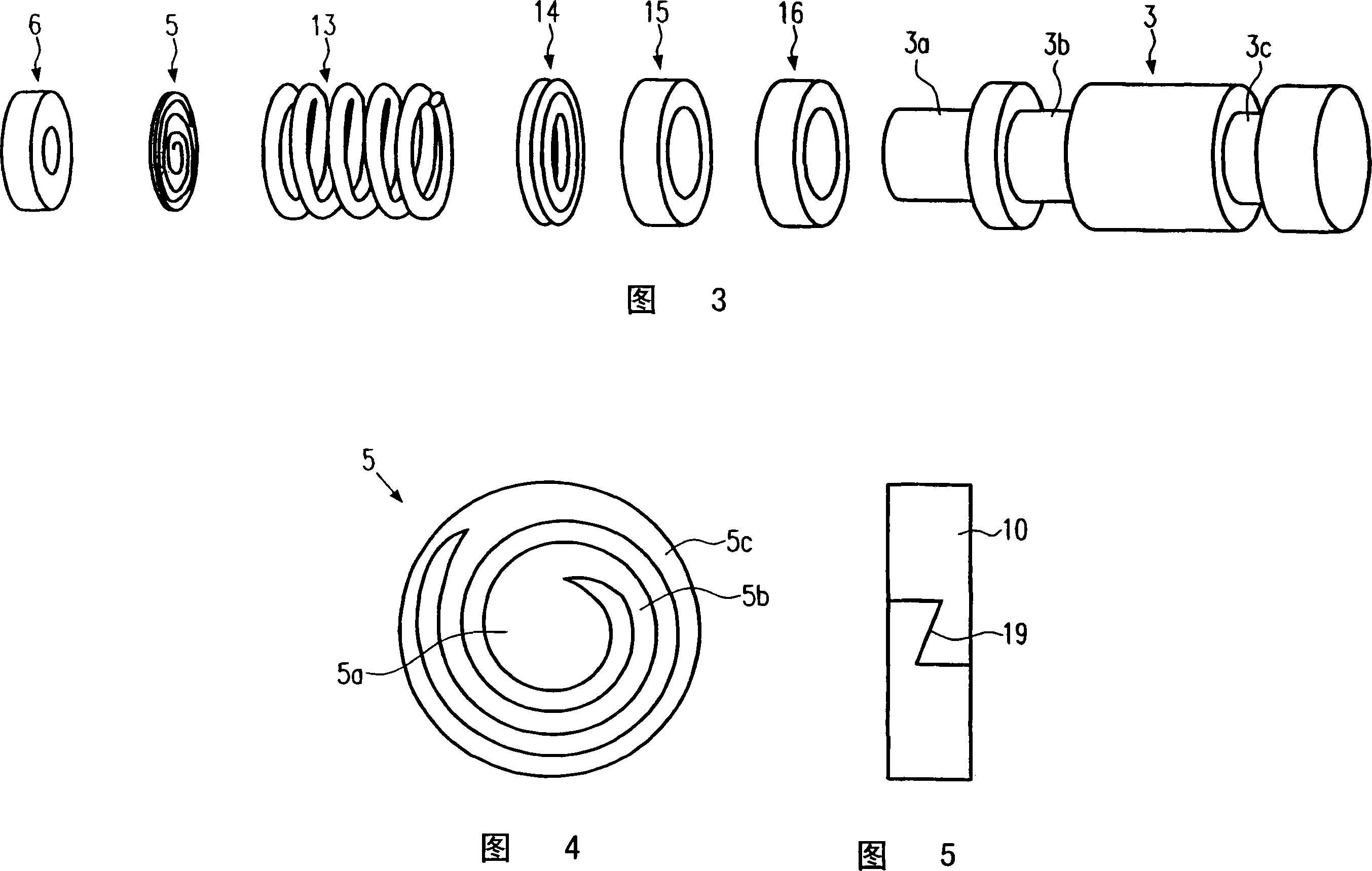
[0028] As can be seen from FIG. 1, a piston pump 1 according to a preferred embodiment of the present invention comprises a cylindrical member 2 having a cylindrical hole 2a. A piston 3, the details of which can be seen in FIG. 3, is arranged in the cylindrical bore 2a. Piston 3 comprises a piston pin 3a and two annular grooves 3b and 3c and is moved by means of an eccentric, not shown.

[0029] A pressure chamber 7 is arranged in the cylindrical bore 2 a, which is hydraulically arranged between the inlet valve 4 and the outlet valve 9 . The inlet valve 4 essentially consists of a spring seal 5 , the details of which are shown in FIG. 4 . As can be seen from FIG. 1, the spring seal 5 is plate-shaped and comprises a disk-shaped sealing area 5a, a spring area 5b and a retaining area 5c. The spring region 5b is a type of coil and conn...


PUM


Abstract

The invention relates to a piston of a pump for a hydraulic fluid flow comprising a reciprocating piston (3) for increasing pressure in a pressure chamber (7) and at least one valve provided with a spring sealing element (5), wherein said spring sealing element (5) comprises a sealing area (5a) and a spring area (5b) for releasing and closing an opening (6a).

Description

technical field [0001] The invention relates to a piston pump with improved pressure building dynamics for conveying hydraulic fluids. Background technique [0002] Different designs of piston pumps are known in the prior art. Radial piston pumps are usually used as piston pumps for vehicle brake systems, in which at least one piston can be moved back and forth by means of an eccentric. Piston pumps of this type are often used in conjunction with electronic stability systems (ESP) or electrohydraulic brakes (EHB). In principle, these known piston pumps have a pressure chamber arranged between the inlet valve and the outlet valve, in which pressure chamber is built up by the movement of the piston. In order to achieve a construction as compact as possible, piston pumps are known in which the hydraulic fluid is guided to the pressure chamber via bores provided in the piston. The inlet valve is arranged in the pressure chamber at the pressure-chamber-side end of the piston. ...

Claims


Application Information

Patent Timeline
Patent Type & Authority Applications(China)
IPC IPC(8): F04B53/10F16K15/02F16K15/04
CPCF04B1/0452F04B53/101F04B53/1037B60T8/4031
Inventor M·胡尔斯特O·克恩莱因
Owner ROBERT BOSCH GMBH
Why Eureka
Try Eureka