
Light receiving device

A light-receiving and light-receiving part technology, applied in semiconductor devices, electrical components, circuits, etc., can solve the problems of difficult miniaturization, good heat dissipation improvement effect, and difficult miniaturization of receiving devices, and achieve high heat dissipation and effective interference shielding effect. Effect

Inactive Publication Date: 2007-06-27
SHARP KK
View PDF2 Cites 2 Cited by
  • Summary
  • Abstract
  • Description
  • Claims
  • Application Information

AI Technical Summary

Problems solved by technology

[0010] That is, in the light receiving device shown in the above i), in order to ensure the distance from the interference source, it is difficult to reduce the size of the receiving device.
In the light receiving device shown in ii) above, since a shielding member is added, there are disadvantages of increased cost, increased assembly process, and difficulty in miniaturization.
[0011] In addition, in the light-receiving device disclosed in JP-A-11-131283, Ni plating is performed on the translucent encapsulating resin except for the light-receiving part, but an additional manufacturing process is necessary for this, and intermediate members such as masking tapes are also required.
In addition, because of the addition of this process, there is a concern that the yield of products will decrease, and due to these reasons, the production cost will inevitably increase.
In addition, regarding the heat dissipation, although the light-transmitting encapsulation resin is passed through from the heat source (light-receiving element) to the Ni-plated part, in general, the heat conduction of the light-transmitting encapsulation resin is not good, so it cannot be said that the heat dissipation improvement effect is good.
[0012] In addition, in the light-receiving device disclosed in Japanese Patent Laid-Open No. 2001-36100, only the surface in the incident direction is shielded for the light-receiving element, and it has no effect on interference entering from other directions.
In addition, since the heat conduction of the flexible substrate is not very good, the heat dissipation is not good, and there is also concern that the light receiving axis will deviate due to the deformation of the substrate at high temperature, etc.

Method used


Image

  • Light receiving device
  • Light receiving device
  • Light receiving device

Examples


Embodiment Construction

[0044] Hereinafter, the present invention will be described in detail based on the illustrated embodiment.

[0045] (First Embodiment)

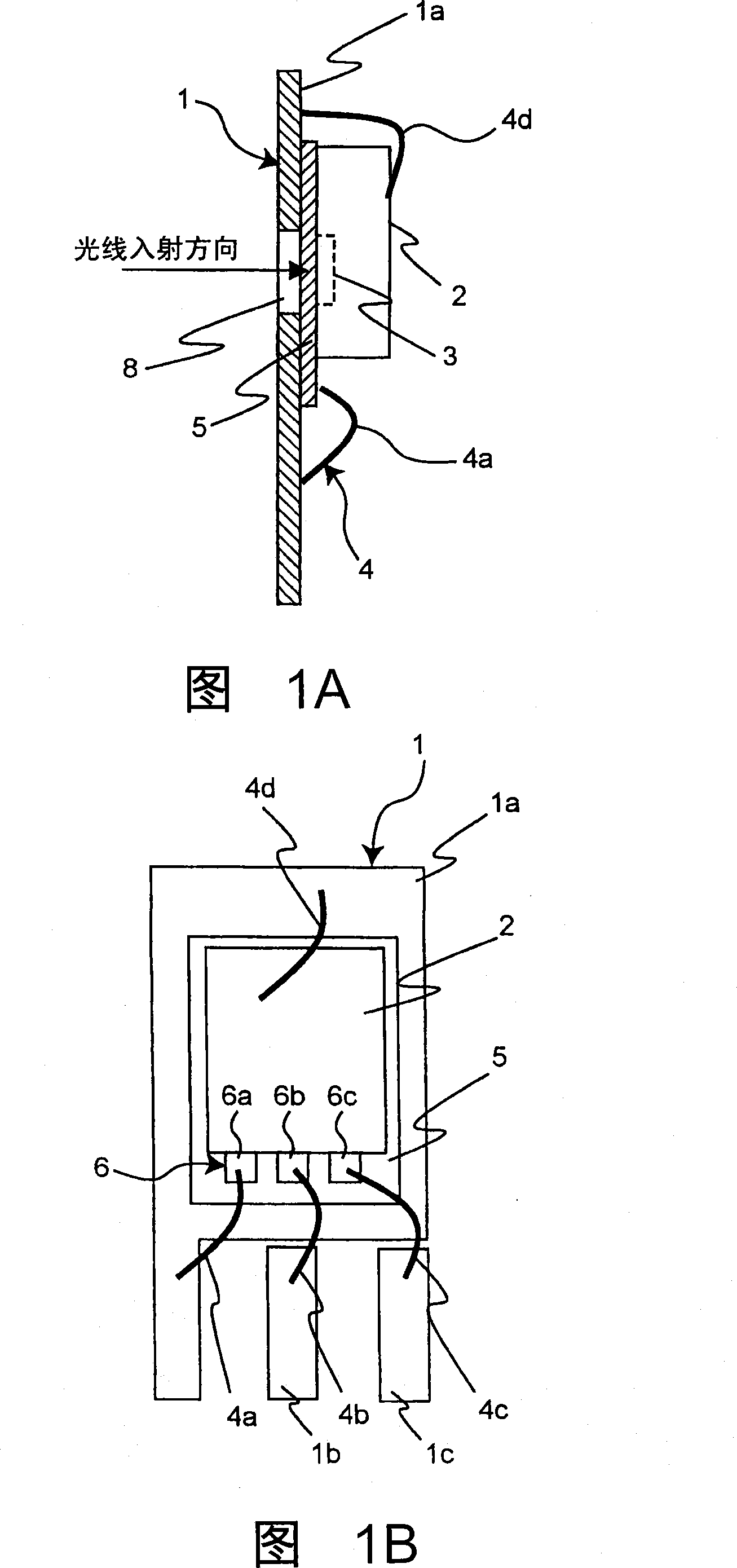
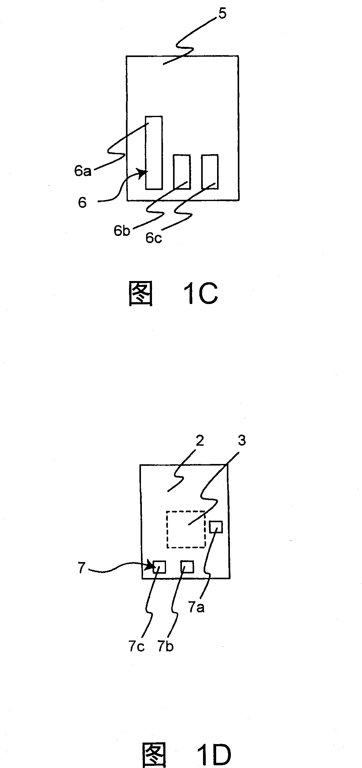
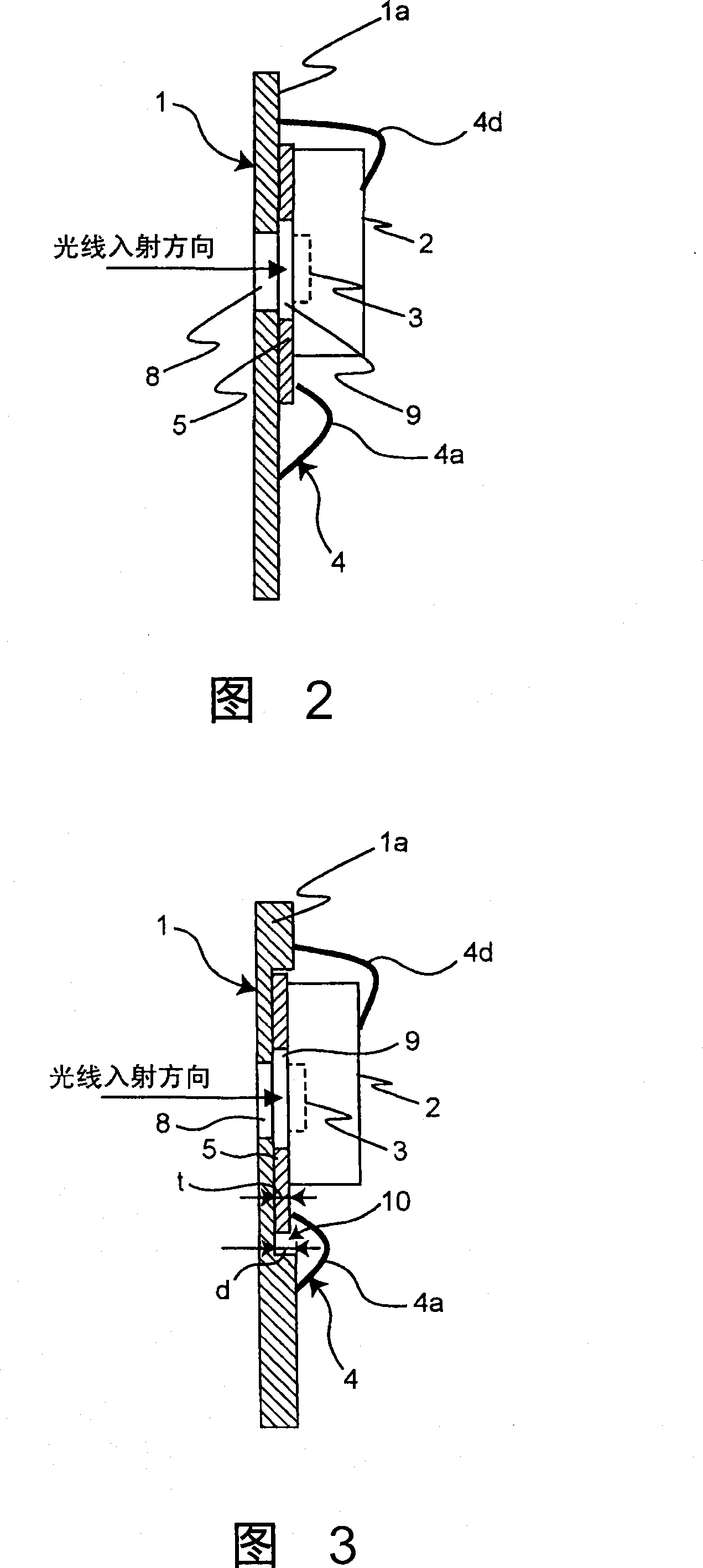
[0046]Fig. 1A is a side sectional view of an embodiment of the light receiving device of the present invention. Fig. 1B is a plan view of the light receiving device of the present invention. The light receiving device includes: a conductive frame 1 having an opening 8; an electrically insulating substrate 5 arranged on one side of the frame 1 and in the vicinity of the opening 8 of the frame 1; and a light receiving portion 3 at the same time The light-receiving element 2 arranged on the side of the substrate 5 opposite to the frame 1 so that the light-receiving portion 3 overlaps the opening 8 of the frame 1.

[0047] The frame 1 is made of a conductive material such as metal, and has a grounded GND frame 1a, a light-receiving output frame 1b connected to a light-receiving output, and a power source frame 1c connected to a power supply voltage. ...


PUM


Abstract

A light receiving device includes a frame (1) and a light receiving element (2) arranged on one plane of the frame (1). Another plane of the light receiving element (2) on the opposite side to the frame (1) and the frame (1) are grounded. Therefore, a GND potential exists on the one plane of the light receiving element (2), and the other plane of the light receiving element (2) also has the GND potential. Thus, the light receiving device which is small, has effective noise shield effects and high heat dissipating characteristic is provided.

Description

Technical field [0001] The present invention relates to, for example, an optical receiving device used in optical communication. Background technique [0002] In recent years, with the increase in the capacity of information and the increase in communication speed, optical communication has been more adopted as an information transmission means. Although optical communication is now used as a high-speed communication means in the communication backbone system, on the other hand, with the informatization of the home, part of the communication between devices in the home also introduces optical communication. In the future, it can be predicted that the use of communications and networks in new fields such as homes and vehicles that effectively utilize its high speed and high reliability will expand. In particular, due to the anti-interference ability or low unwanted radiation interference of optical communication, it is showing its skills as a means of communication between devices...

Claims


Application Information

Patent Timeline
Patent Type & Authority Applications(China)
IPC IPC(8): H01L31/02
CPCH01L31/024H01L31/0203H01L2924/19107H01L2224/48257H01L2924/3025H01L2224/48247H01L2224/48091H01L2924/00014H01L2924/00
Inventor 松尾顺向
Owner SHARP KK
Learn More