Cylinder battery casing laser welding fixture

Active Publication Date: 2007-07-04
SHENZHEN BAK POWER BATTERY CO LTD
View PDF1 Cites 43 Cited by
  • Summary
  • Abstract
  • Description
  • Claims
  • Application Information

AI Technical Summary

Problems solved by technology

However, when the above device is used for welding, the round runout of the battery is relatively large, and the

Method used


Image

  • Cylinder battery casing laser welding fixture
  • Cylinder battery casing laser welding fixture
  • Cylinder battery casing laser welding fixture

Examples


Embodiment Construction

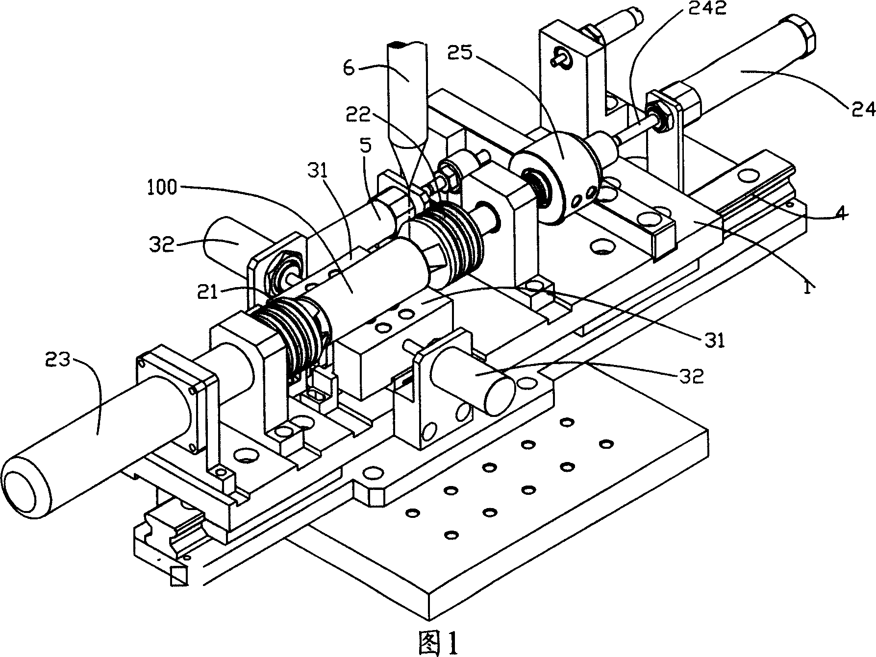
[0021] Please refer to FIG. 1 , which is a preferred embodiment of the present invention. The cylindrical battery casing laser welding jig mainly includes a workbench 1 , a clamping mechanism and a supporting mechanism.

[0022] The clamping mechanism is located on the workbench 1 and includes two chucks 21 , 22 , a first driving device 23 and a second driving device 24 . The two clamps 21 and 22 are used to clamp both ends of the battery 100 , one clamp 21 is connected to the first driving device 23 , and the other clamp 22 is connected to the second driving device 24 . The first driving device 23 is used to drive the chucks 21 and 22 to rotate around their own axis as the rotation axis. In this embodiment, the first driving device 23 is a servo motor. This second driving device 24 is used to drive chuck 22 close to or away from another chuck 21, in the present embodiment, second driving device 24 is an air cylinder, its piston rod 242 and the mounting handle of chuck 22 (not...


PUM


Abstract

The invention involves a cylindrical battery shell laser welding fixture which includes workstation, clamping device and support device; said clamping device is equipped on the workstation which is used for clamping two clamping heads of two ends of clamping batteries and the first driver device for driving the second clamping head rotating using its shaft line as rotating axle; said support device is equipped on said workstation and is equipped with support surface matching or arranged with the cylinder face of battery. The support surface of support device can ensure the battery axis is coincidence with the rotation axis of welding fixture using said devices when clamping battery, the round jumping amount of battery is small when the clamping head rotating to improving the laser welding quality and reducing the leakage rate of battery.

Description

【Technical field】 [0001] The invention relates to a cylindrical battery production equipment, in particular to a laser welding jig for a cylindrical battery casing. 【Background technique】 [0002] Traditional cylindrical lithium-ion batteries are usually sealed by rolling and flanging. The sealing rolling groove of cylindrical batteries using this sealing method takes up a lot of space, resulting in a small battery capacity. [0003] In order to make full use of the internal space of the battery and increase the battery capacity, the industry adopts laser welding sealing technology. The technology is divided into two types: vertical welding and flat welding. The laser beam of vertical welding is welded along the axial direction of the cylindrical battery, and the laser beam of flat welding is welded along the radial direction of the cylindrical battery. At present, flat welding is more common. [0004] The applicant applied for a Chinese utility model patent on May 25, 2005...

Claims


Application Information

Patent Timeline
IPC IPC(8): B23K37/053B23K26/20B23K26/42B23K26/21B23K26/70
Inventor 吴飞超卢红波祁强
Owner SHENZHEN BAK POWER BATTERY CO LTD
Why Eureka
Try Eureka