Twin clutch device

A dual clutch, clutch technology, applied in the direction of clutch, friction clutch, mechanical drive clutch, etc., can solve the problems of increasing the number of parts, the size of the dual clutch, increasing the number of assembly hours, etc., and achieve the effect of reliable disconnection and connection.

Inactive Publication Date: 2007-07-04
HONDA MOTOR CO LTD
View PDF3 Cites 12 Cited by
  • Summary
  • Abstract
  • Description
  • Claims
  • Application Information

AI Technical Summary

Problems solved by technology

[0009] However, in the structure in which the two outer clutches are fixed with screws, that is, in the case of the double clutch disclosed in JP-A-61-153023, since the screw fixing increases the outer peripheral diameter of the outer clutch, not only the size of the double clutch is large, And increase the number of parts and increase the number of assembly man-hours

Method used


Image

  • Twin clutch device
  • Twin clutch device
  • Twin clutch device

Examples


Embodiment Construction

[0044] Hereinafter, an embodiment for realizing the present invention will be described based on an embodiment of the present invention shown in the drawings.

[0045] 1 to 9(b) are views showing an embodiment of the present invention.

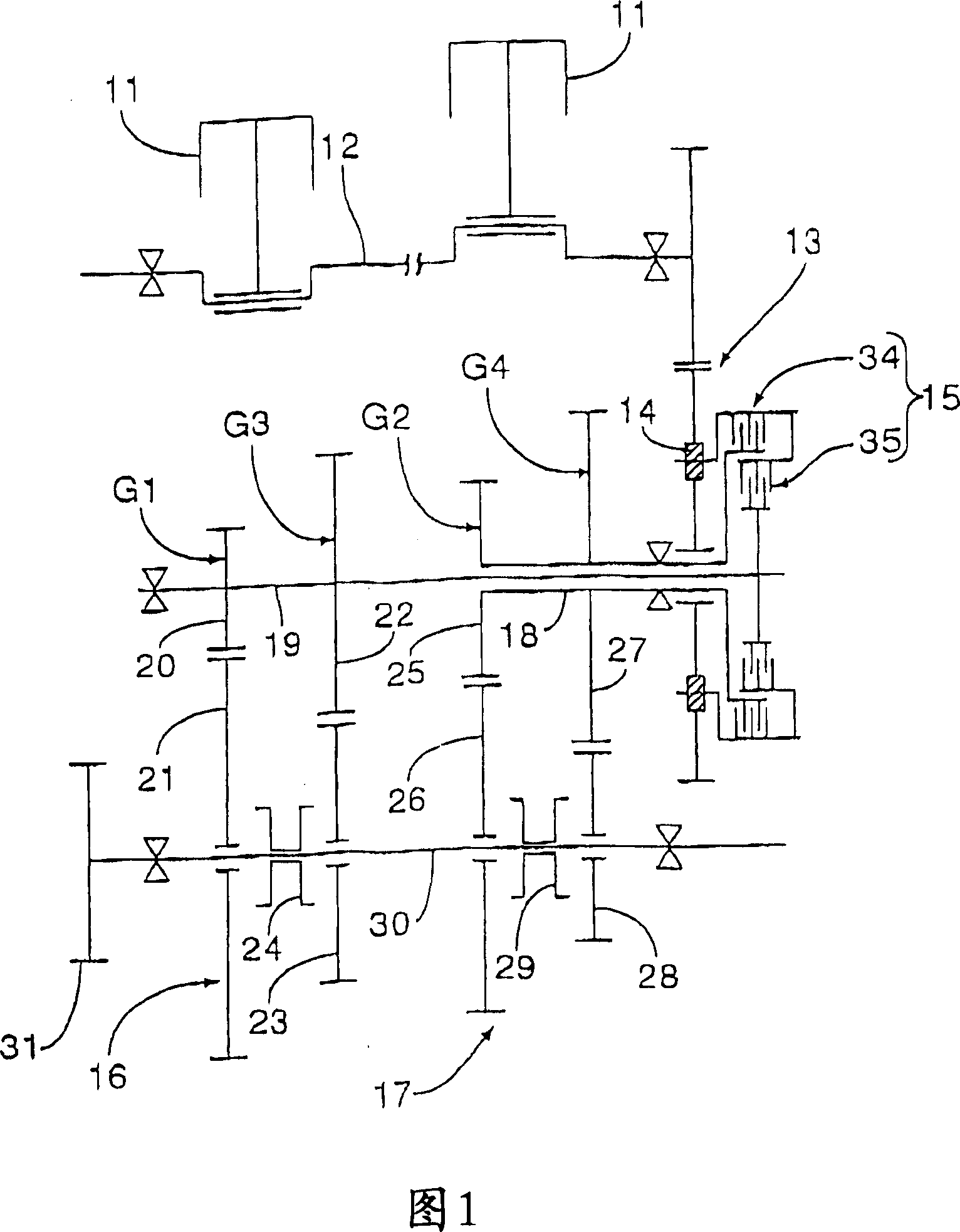
[0046] As shown in FIG. 1, a plurality of pistons 11, 11, . . . are provided, for example, for a multi-cylinder engine mounted on a motorcycle. Each piston is connected to a crankshaft 12 which is rotatably supported on a crankcase not shown in the figures. The rotational power of the crankshaft 12 is input to the dual clutch device 15 through the main gear reduction device 13 and the rubber damper 14 . On the other hand, the crankcase accommodates an odd shift gear train 16, which includes odd shift gear trains, for example, first and third shift gear trains G1, G3 that can be selectively established, and the crankshaft The housing also accommodates an even shift gear train 17 which includes even shift gear trains, for example, second and f...


PUM


Abstract

A twin clutch device wherein a second clutch is arranged coaxially and radially inside of a first clutch outer which forms an annular plate portion. One clutch inners of both clutches is arranged between a clutch member which constitutes a portion of the outer of the first and second clutches and an annular plate portion. Lifter pins have axes arranged parallel to a rotary axis of first and second clutches and axially movably penetrate both clutch inners to bring one ends thereof into contact with pressure plates. First and second drive control members are capable of applying control forces to disconnect the first and second clutches against spring forces of first and second clutch springs. A second clutch outer is rotated together with the first clutch outer and is arranged coaxially with the first clutch. A pair of clutch outers are connected in a relatively non-rotatable manner with each other.

Description

[0001] Cross-references in relation to applications [0002] This application claims priority under 35USC 119 to Japanese Patent Applications Nos. 2005-377451, 2005-377452, and 2005-377453 filed on December 28, 2005, the entire contents of which are hereby incorporated by reference. technical field [0003] A dual clutch comprising a multi-disc type first clutch comprising a first outer clutch formed in a bottomed cylindrical shape, having an annular plate portion at one end of the first outer clutch, which is transmitted by a power source power to rotate. The second clutch of multi-disc type includes a second outer clutch that rotates together with the first outer clutch and is coaxially disposed within the first clutch in a radial direction. One of the inner clutches belonging to the first and second clutches, respectively, is disposed between a clutch member constituting a part of the first and second outer clutches and the annular plate portion, the clutch member being ro...

Claims


Application Information

Patent Timeline
Patent Type & Authority Applications(China)
IPC IPC(8): F16D13/56B60K17/02
Inventor 塚田善昭三堀敏正黑木正宏
Owner HONDA MOTOR CO LTD
Why Eureka
Try Eureka