

Method for operation of a braking system for a motor vehicle
A technology for parking brakes and motor vehicles, which is applied in the direction of brakes, brake transmission devices, automatic starting devices, etc., and can solve problems such as incomplete release of electric parking brakes
- Summary
- Abstract
- Description
- Claims
- Application Information
AI Technical Summary
Problems solved by technology
Method used
Image

Examples
Embodiment Construction
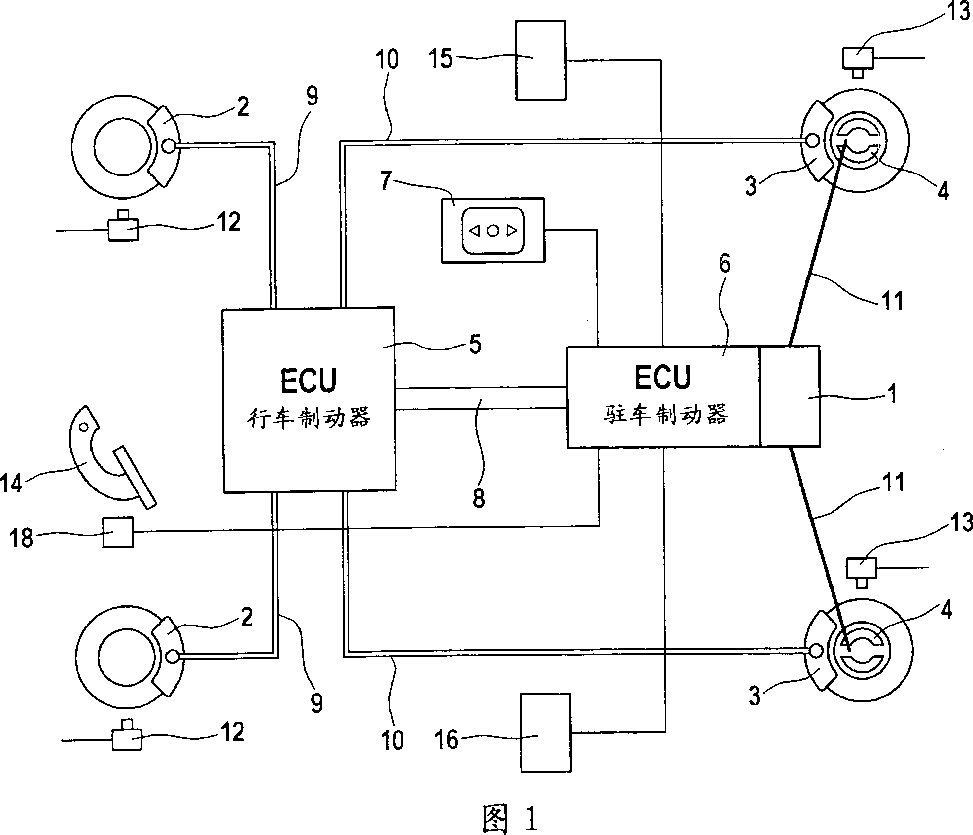
[0016] A circuit diagram of a hydraulic brake system is schematically shown in FIG. 1 . The hydraulic braking system has wheel brakes 2 on the first axle, the front axle, which can be applied with pressure during service braking via hydraulic lines 9 . In order to control the desired braking deceleration and to implement anti-lock brake regulation (ABS), the wheels of the front axle are assigned wheel speed sensors 12, the output signals of which are fed to the electronic control and regulation unit (ECU) 5 . The electronic control and regulating unit 5 is assigned to the service brake system. Wheel brakes 3 are also arranged on the second, ie rear, axle, which can be acted upon with pressure during service braking via the second hydraulic line 10 . The rotational speeds of the wheels of the rear axle are detected by wheel rotational speed sensors 13 and supplied to the aforementioned electronic control and regulating unit 5 . Furthermore, the wheels of the rear axle have e...
PUM
 Abstract
Description
Claims
Application Information