
Antenna component

A chip antenna, antenna technology, applied in the direction of antenna, resonant antenna, electrical short antenna, etc., can solve the problem of unsatisfactory antenna efficiency, and achieve the effect of simple structure and high field strength

Active Publication Date: 2007-07-04
PULSE FINLAND
View PDF2 Cites 20 Cited by
  • Summary
  • Abstract
  • Description
  • Claims
  • Application Information

AI Technical Summary

Problems solved by technology

Therefore the efficiency of the antenna is not satisfactory

Method used


Image

  • Antenna component
  • Antenna component
  • Antenna component

Examples


Embodiment Construction

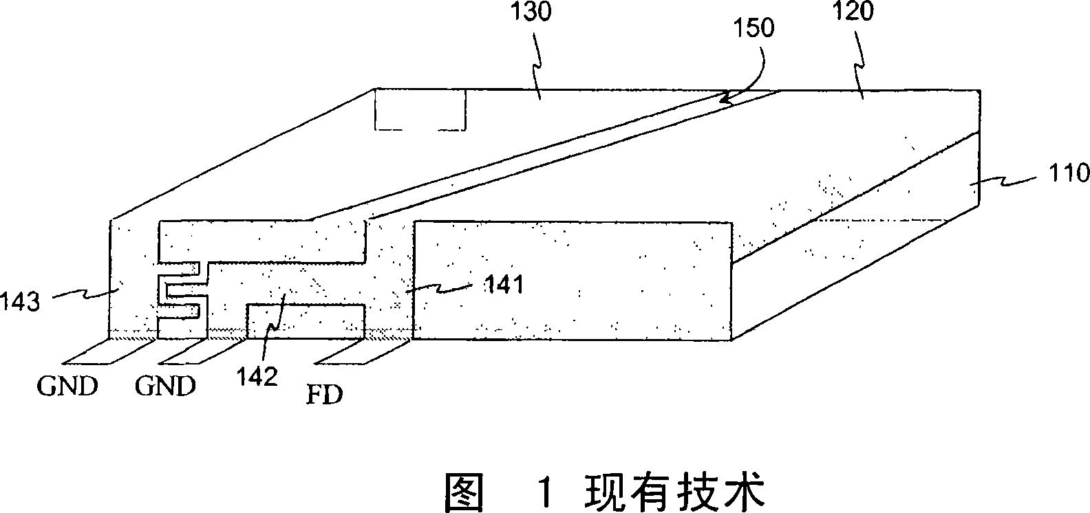
[0019] FIG. 1 has already been explained in connection with the description of the prior art.

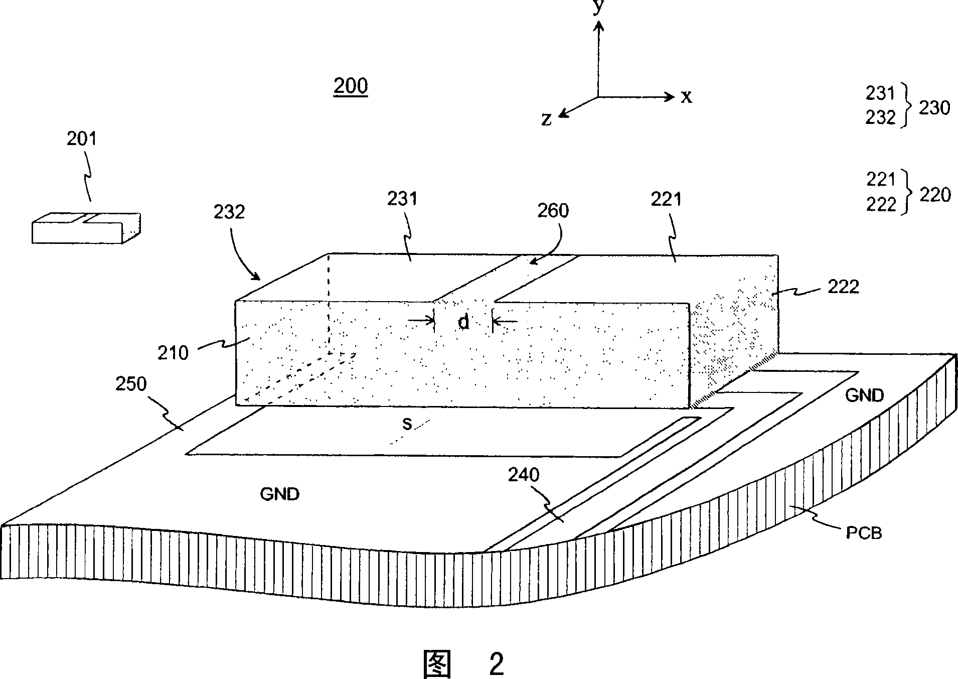
[0020] Fig. 2 shows an example of a chip antenna according to the present invention. The antenna 200 comprises a dielectric substrate chip and two radiating elements on its surface, one of which is connected to the feeding conductor of the antenna and the other is an electromagnetic feeding parasitic element, like in the known antenna of FIG. 1 . However, there are several structural and functional differences between those antennas. In the antenna according to the present invention, wherein the slot separating the radiating elements is between the open ends of the elements and not between the lateral edges, and the parasitic element passes through the coupling which predominates over the slot and not through the ground conductor of the parasitic element and the feed The coupling between electrical conductors to obtain its feed. The first radiating element 220 of the antenna 200 i...


PUM


Abstract

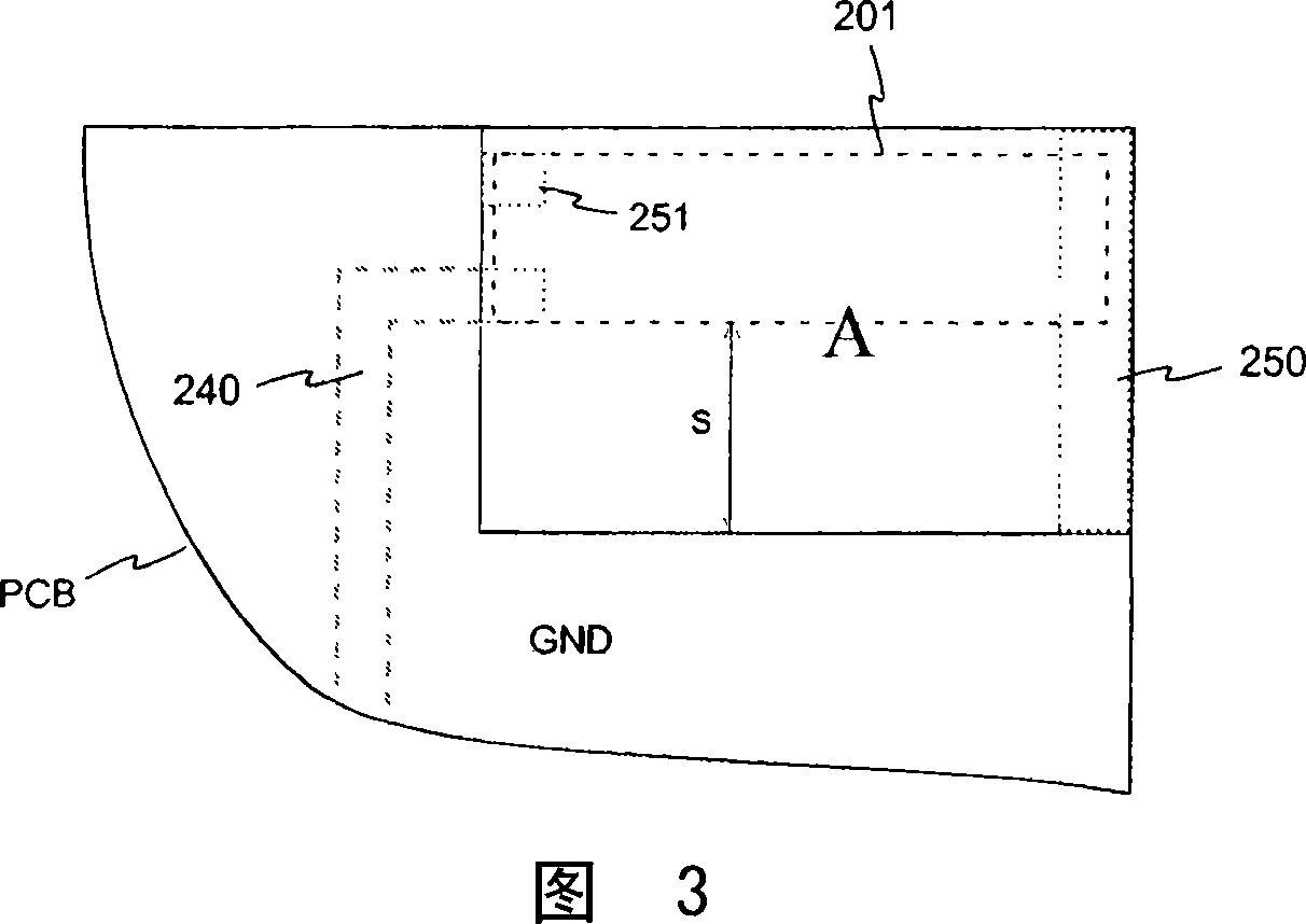
The invention relates to an antenna in which the radiators are conductor coatings of a dielectric substrate chip (210). There are two radiators (220, 230), and they are of the same size and symmetrical so that each covers one of the opposite heads of a rectangular substrate chip and part of the upper surface. In the middle of the upper surface between the elements there remains a slot (260), over which the elements have an electromagnetic coupling with each other. The chip component (201) is mounted on a circuit board (PCB), the conductor pattern of which is part of the whole antenna structure. There is no ground plane (GND) under the chip or on its sides up to a certain distance (s). The lower edge of one radiator (220) is galvanically coupled to the antenna feed conductor on the circuit board, and at another point to the ground plane, whereas the lower edge of the opposite, parasitic radiator (230) is galvanically coupled only to the ground plane. The parasitic radiator gets its feed through said electromagnetic coupling, and both elements resonate equally strongly at the operating frequency. The antenna is tuned and matched without discrete components by changing the width (d) between the radiating elements and by shaping the conductor pattern of the circuit board near the chip component. The efficiency of the antenna is good in spite of the dielectric substrate, and its omnidirectional radiation is excellent.

Description

technical field [0001] The invention relates to an antenna in which the radiator is a conductive coating of a dielectric chip. The chip will be mounted on the radio's circuit board, which is part of the overall antenna structure. Background technique [0002] In a radio device of small size, such as a mobile phone, the antenna or antennas are preferably located inside the cover of the device, and it is a natural aim to keep them as small as possible. An internal antenna usually has a planar structure, so it includes a radiating plane and a ground plane below it. There is also a variant of the monopole antenna in which the ground plane is not below the radiation plane but further to one side. In both cases, the size of the antenna can be reduced by fabricating the radiating plane on the surface of the dielectric chip instead of making it air-insulated. The higher the dielectricity of the material, the smaller the physical size of an antenna element of a given electrical si...

Claims


Application Information

Patent Timeline
Patent Type & Authority Applications(China)
IPC IPC(8): H01Q1/38H01Q1/24H01QH01Q1/22H01Q9/04
CPCH01Q9/0421H01Q1/38H01Q1/2283H01Q1/243H01Q13/106
Inventor J·索尔瓦拉
Owner PULSE FINLAND
Learn More