Electric motor

A technology of electric motor and electric motor casing is applied in the field of electric motor to achieve the effect of avoiding motor damage, small structure space and improving heat loss

Active Publication Date: 2010-10-06
BROSE FAHRZEUGTEILE GMBH & CO KG HALLSTADT (DE)
View PDF8 Cites 0 Cited by
  • Summary
  • Abstract
  • Description
  • Claims
  • Application Information

AI Technical Summary

Problems solved by technology

So the cooling air flow can only play a very limited role

Method used


Image

  • Electric motor
  • Electric motor
  • Electric motor

Examples


Embodiment Construction

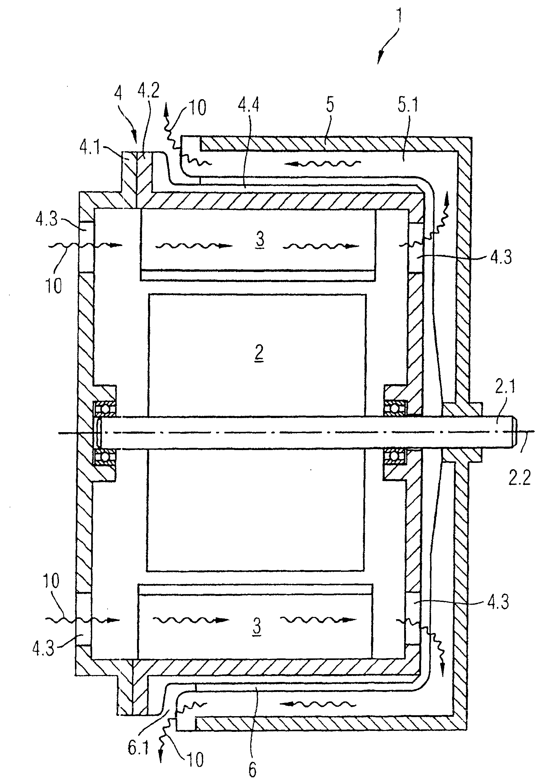
[0033] figure 1 A greatly simplified schematic diagram of an electric motor 1 according to the invention is shown.

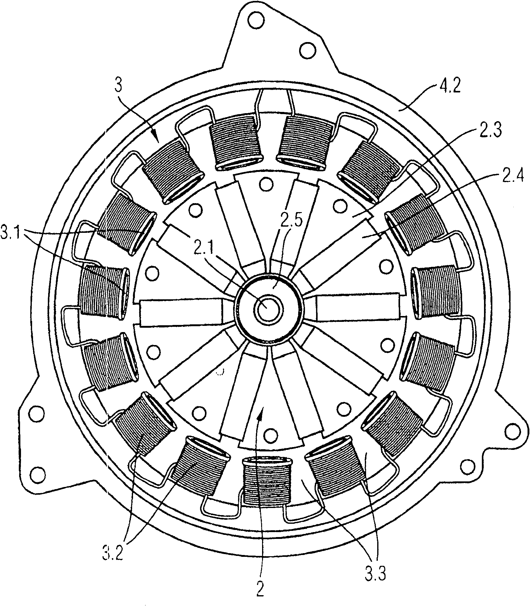
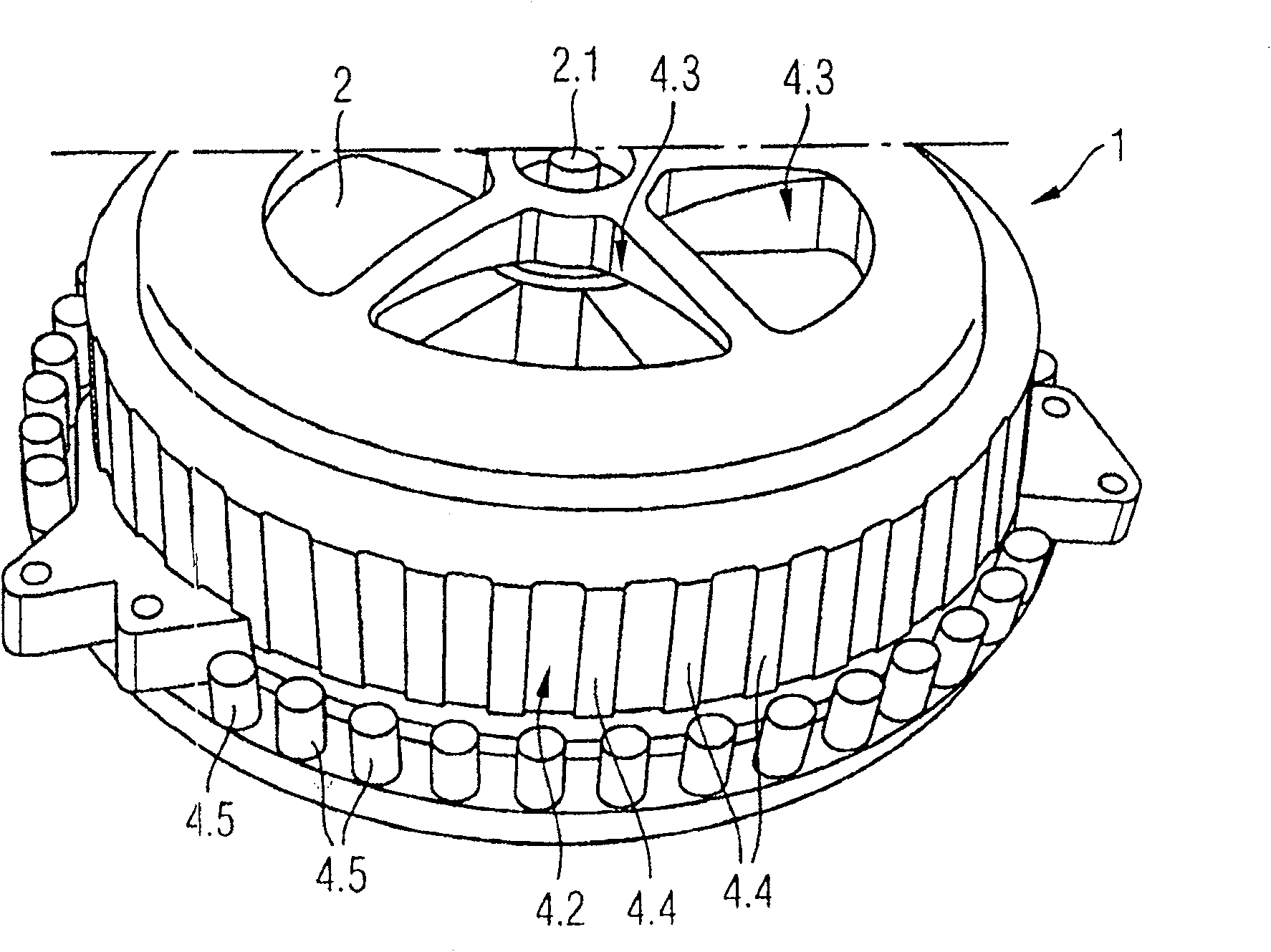
[0034] The electric motor 1 basically has an inner rotor 2 , an outer stator 3 , a motor housing 4 and a ventilation hood 5 . The inner rotor 2 is connected in a rotationally fixed manner to a rotor shaft 2 . 1 and is supported rotatably about a rotor axis 2 . 2 via this rotor shaft in the motor housing 4 . The fan bell 5 is likewise connected in a rotationally fixed manner to the rotor shaft 2.1 and rotates with the inner rotor 2 during operation. The motor housing 4 consists of a housing housing 4.2 and a housing cover 4.1 and has ventilation openings 4.3. The ventilation holes 4.3 are arranged at the same radial distance from the rotor axis 2.1 as the wound stator teeth of the outer stator 3. The ventilation hood 5 surrounds the motor housing 4 in the shape of a cup and is arranged at both an axial and a radial distance from the outside of the motor housin...


PUM


Abstract

The invention relates to an electromotor comprising an external stator, and a ventilation vessel which is used to produce a cool air flow in order to properly cool the electromotor. In order to cool the electromotor in an improved manner, an air flow is guided, by means of a ventilator vessel, along the outer surface of the motor housing, through the inside of the housing of the electromotor and through an air gap formed between an intermediate housing wall and a ventilation vessel.

Description

technical field [0001] The invention relates to an electric motor with a fixed outer stator, an inner stator and a self-cooling device, for example as a radiator fan drive in motor vehicles. Background technique [0002] Reliable electric motor operation requires materials used that do not overheat under the given operating conditions. It must be taken into account that overheating does not occur during operation of the motor at maximum power loss at ambient temperature. Failure to observe this can lead to a shortened service life of the motor or to the complete scrapping of the motor. [0003] The cooling or dissipation of the electric motor, ie the dissipation of lost heat, in particular from the coils and electromagnetically active ferrous materials, is therefore of particular importance. [0004] In the case of electric motors, which are used, for example, to drive fans, it is known to use a pressure difference between the air inlet and the air outlet of the motor to f...

Claims


Application Information

Patent Timeline
Patent Type & Authority Patents(China)
IPC IPC(8): H02K9/14F04D25/08H02K9/06
CPCH02K9/14H02K9/06F04D25/082Y10T29/49012F04D29/5806
Inventor P·德菲里皮斯M·厄杰兰地D·克默P·S·麦克伦南H·雷地尔伯杰
Owner BROSE FAHRZEUGTEILE GMBH & CO KG HALLSTADT (DE)
Why Eureka
Try Eureka