Test method for liquid crystal display panel

A liquid crystal display and panel technology, applied in static indicators, electronic circuit testing, instruments, etc., can solve problems such as waste, unknowability, and reduced output

Active Publication Date: 2007-07-11
AU OPTRONICS CORP
View PDF0 Cites 17 Cited by
  • Summary
  • Abstract
  • Description
  • Claims
  • Application Information

AI Technical Summary

Problems solved by technology

Therefore, the tester cannot know whether there is a defect after the defect point 102. If the grid line after the defect point 102 has no defects, the discarding of the panel will form a waste of materials and reduce the output

Method used


Image

  • Test method for liquid crystal display panel
  • Test method for liquid crystal display panel
  • Test method for liquid crystal display panel

Examples


Embodiment Construction

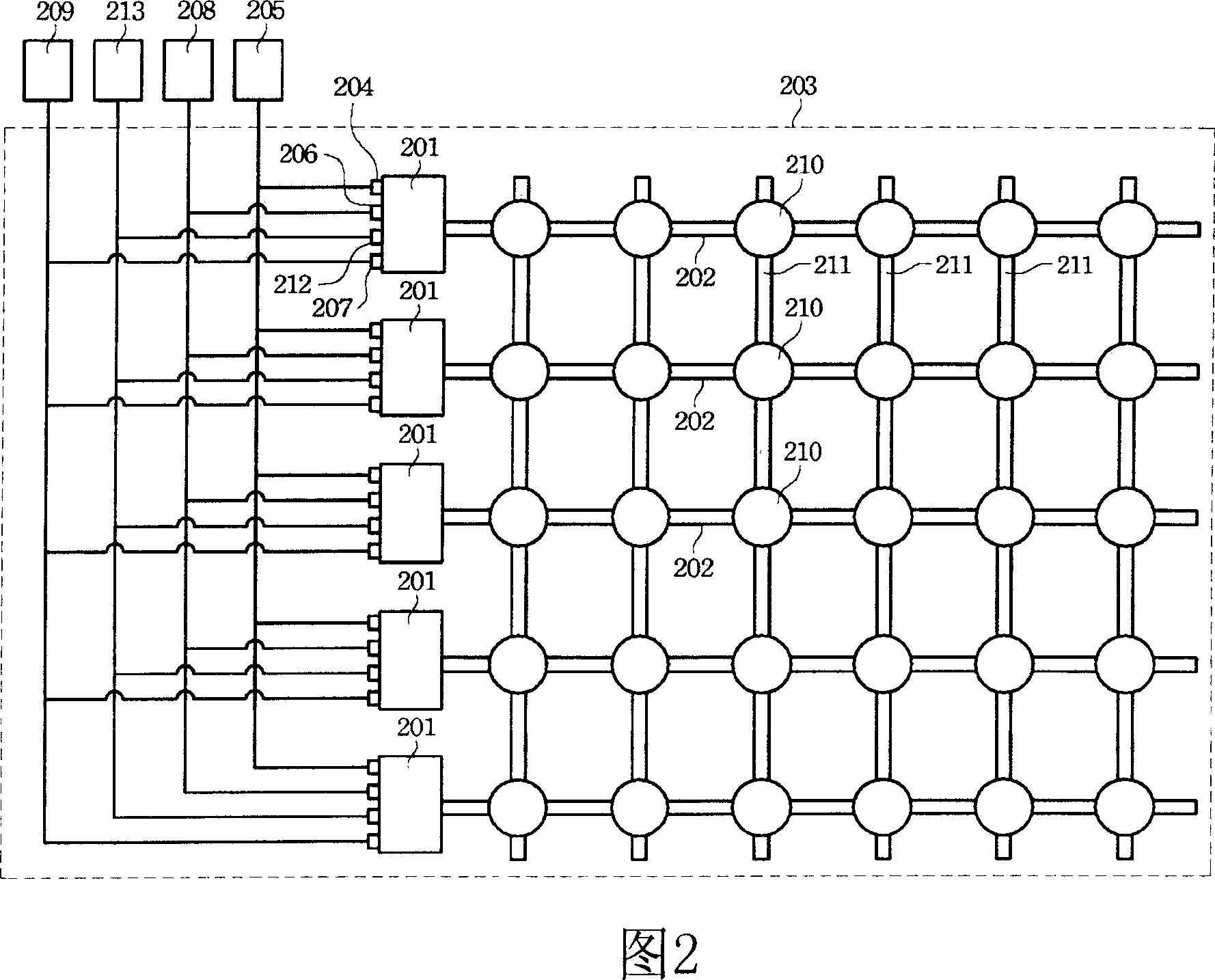
[0055] The invention provides a testing method of a liquid crystal display panel, which is used for simultaneously testing the thin film transistors on multiple gate lines when the grid driving circuit is integrated on the liquid crystal display panel. The first embodiment of the present invention is to electrically connect the positive phase timing input end, the negative phase timing input end and the start signal input end of the gate driver of the selected area on the liquid crystal display panel to the corresponding test pads respectively. After the gate driver in the selected area turns on the gate lines, all the pixels represented by the TFTs in the selected area can be tested.

[0056] Please refer to FIG. 2 , which shows a schematic diagram of a selected area of ​​a liquid crystal display panel according to a first embodiment of the present invention. The gate driver 201 and the gate lines 202 are integrated on the panel glass 203 . The positive-phase timing input en...


PUM


Abstract

A way for testing LCD panel combines the LCD panel to grid through grid drive circuit, at least inputting positive and negative phase time sequence and lower pull signal to selected zone grid driver positive sequence input end, negative time sequence input end and lower pull signal input end. Inputting start signal at the same time to grid driver start signal input end to start selected area grid, and starting the selected thin film transistor at the same time. Send a testing signal by all data cables. It can also be used for local testing. It divides the panel into several zones with different testing areas.

Description

technical field [0001] The invention relates to a testing method of a liquid crystal display panel, wherein a grid driving circuit is integrated on the liquid crystal display panel. Background technique [0002] As the electronic commodity market is booming day by day, the demand for liquid crystal display panels is also increasing. This demand is because many electronic products use liquid crystal displays (Liquid Crystal Display, LCD), such as TV screens, computer screens, and mobile phone screens. Correspondingly, the testing of liquid crystal display panels has also become a key step in the mass production of liquid crystal display panels. Currently, testing methods for liquid crystal display panels include full contact testing and shorting bar testing. The advantage of the full contact test method is its good test function, but it consumes a lot of chip test time. The short-circuit bar test method can shorten the test time, because this test method divides all gate l...

Claims


Application Information

Patent Timeline
Patent Type & Authority Applications(China)
IPC IPC(8): G09G3/00G09G3/36G01R31/00G01R31/28G02F1/13
Inventor 俞善仁陈静茹
Owner AU OPTRONICS CORP
Why Eureka
Try Eureka