A magnetic self-perpetuating relay for the over current protection

A magnetic latching relay and overcurrent protection technology, applied in the direction of electromagnetic relays, relays, detailed information of electromagnetic relays, etc., can solve problems such as relay and power supply circuit burnout, safety accidents, and electronic detection devices not being able to protect, and achieve protection The effect of circuit loops

Inactive Publication Date: 2010-10-06
陆德昌
View PDF4 Cites 1 Cited by
  • Summary
  • Abstract
  • Description
  • Claims
  • Application Information

AI Technical Summary

Problems solved by technology

However, in the circuit where the magnetic latching relay is actually applied, in order to have the necessary safety protection for the circuit, an electronic detection device is generally used to achieve the purpose of overcurrent protection on the circuit, but when the circuit is short-circuited, the electronic detection device cannot be used. Due to the protective effect, the relay and power supply circuit will be burned quickly, causing safety accidents and reducing the safety and reliability of the load circuit

Method used


Image

  • A magnetic self-perpetuating relay for the over current protection
  • A magnetic self-perpetuating relay for the over current protection
  • A magnetic self-perpetuating relay for the over current protection

Examples


Embodiment Construction

[0013] The present invention will be further described below in conjunction with the accompanying drawings.

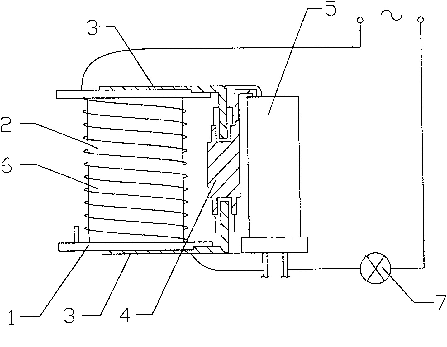
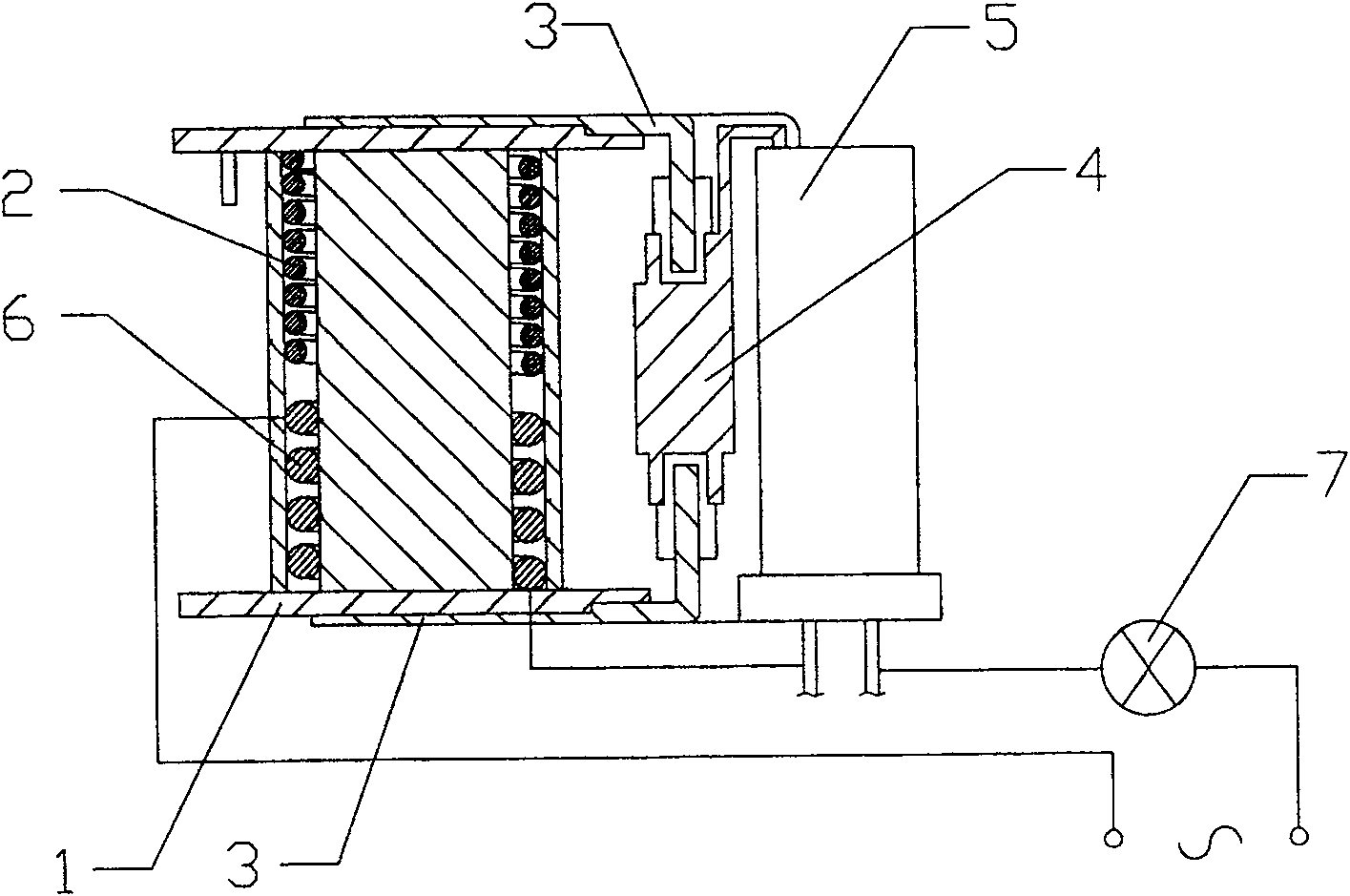
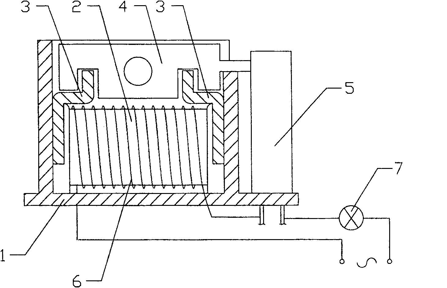
[0014] according to figure 1 and figure 2 As shown, the magnetic latching relay with overcurrent protection of the present invention includes a base 1 and an electromagnetic coil 2 disposed on the base 1 , and an iron core is generally provided in the middle of the electromagnetic coil 2 . A yoke 3 is provided at both ends of the base 1, and a driving arm assembly 4 is provided between the two yokes 3. The driving arm assembly 4 is movably positioned between the two yokes through a connecting piece, and generally has a magnetic Steel, wherein, the drive arm assembly 4 can be a rotary structure, such as figure 1 and figure 2 As shown, it can also be a straight mobile structure, such as image 3 and Figure 4 shown. One side of the base 1 is provided with a contact piece, which can be a double-reed structure or a multi-reed structure, and includes at least one se...


PUM


Abstract

This invention discloses one magnetic keep relay with overflow protection, which comprises base socket and electromagnetic coil on socket, wherein, the base socket two ends are set with yoke iron; two irons are set with drive arm bus between; one side of base socket is set the drive arm bus trigger slice. The invention is characterized by the following: the said electromagnetic line loop is set with overflow protection coil with two ends connected to supply circuit and load, and trigger slices.

Description

technical field [0001] The invention relates to the field of magnetic latching relays, in particular to a magnetic latching relay with overcurrent protection. Background technique [0002] At present, the structure of the common magnetic latching relay generally includes a base, an electromagnetic coil and yokes arranged at both ends of the machine base, a rocker arm is arranged between the two yokes, and a moving reed and a static spring are arranged on one side of the machine base. The seesaw arm drives the reed to move through the middle connecting block. When the electromagnetic coil is fed with pulse currents in different directions, the magnetic force generated by it will make the swing arm swing, and the connecting block and the moving reed will swing left and right driven by the swing arm, thereby realizing the contact between the moving reed and the static spring. to achieve the closure or disconnection of the control circuit, and then the magnetic latching relay w...

Claims


Application Information

Patent Timeline
Patent Type & Authority Patents(China)
IPC IPC(8): H01H51/01H01H83/20
CPCH01H50/24H01H50/443
Inventor 陆德昌
Owner 陆德昌
Why Eureka
Try Eureka