System and method for control of loop alignment in adaptive feed forward amplifiers

A technology for controlling loops and amplifiers, applied in the directions of amplifiers, parts of amplifiers, electrical components, etc., which can solve the problems of limited processing power and failure to achieve fast and accurate loop convergence.

Inactive Publication Date: 2007-07-11
INTEL CORP
View PDF2 Cites 1 Cited by
  • Summary
  • Abstract
  • Description
  • Claims
  • Application Information

AI Technical Summary

Problems solved by technology

Both approaches have disadvantages in practical systems employing control processors with limited processing power and where fast loop ali

Method used


Image

  • System and method for control of loop alignment in adaptive feed forward amplifiers
  • System and method for control of loop alignment in adaptive feed forward amplifiers
  • System and method for control of loop alignment in adaptive feed forward amplifiers

Examples


no. 1 example

[0126] Figure 6 shows a first embodiment of the alignment and step update process. In the first embodiment, there are three methods of calculating alignment adjustment. To select the correct method, the process tests whether the descent direction is undetermined and whether the descent direction has been reversed from its most recent value. The two closest non-collinear descent directions are retrieved (603). If the nearest non-collinear drop θ nc (k) is undetermined, then the alignment adjustment is calculated (645) according to the following equation:

[0127] ( Δα k , Δφ k ) = ( α k - 2 , φ k ...

no. 2 example

[0154] Figure 7 shows a second embodiment of alignment and step size updating. The main difference is that it chooses the step size in terms of eliminating the remainder: i.e.,

[0155] the s k =f{P k} Equation 36

[0156] Where f{} is a specific function.

[0157] In a second embodiment, the nearest non-collinear descent direction value and measured value P k (703). Descent direction is tested (706). If the direction is not determined, then the alignment adjustment determined by Equation 26 is used (718). The alignment is updated (721) using Equation 25, and the discount factor is set to unity (β k = 1).

[0158] If the direction of descent is determined (706), then the step size is calculated using the mapping in Equation 36 (709). The alignment adjustment is based on Equation 23 (712). The alignment is updated (715) using Equation 25, and the discount factor is set to 0.7 (β k = 0.7). Although the mapping in Equation 36 can be obtained experimentally, it can be ...


PUM


Abstract

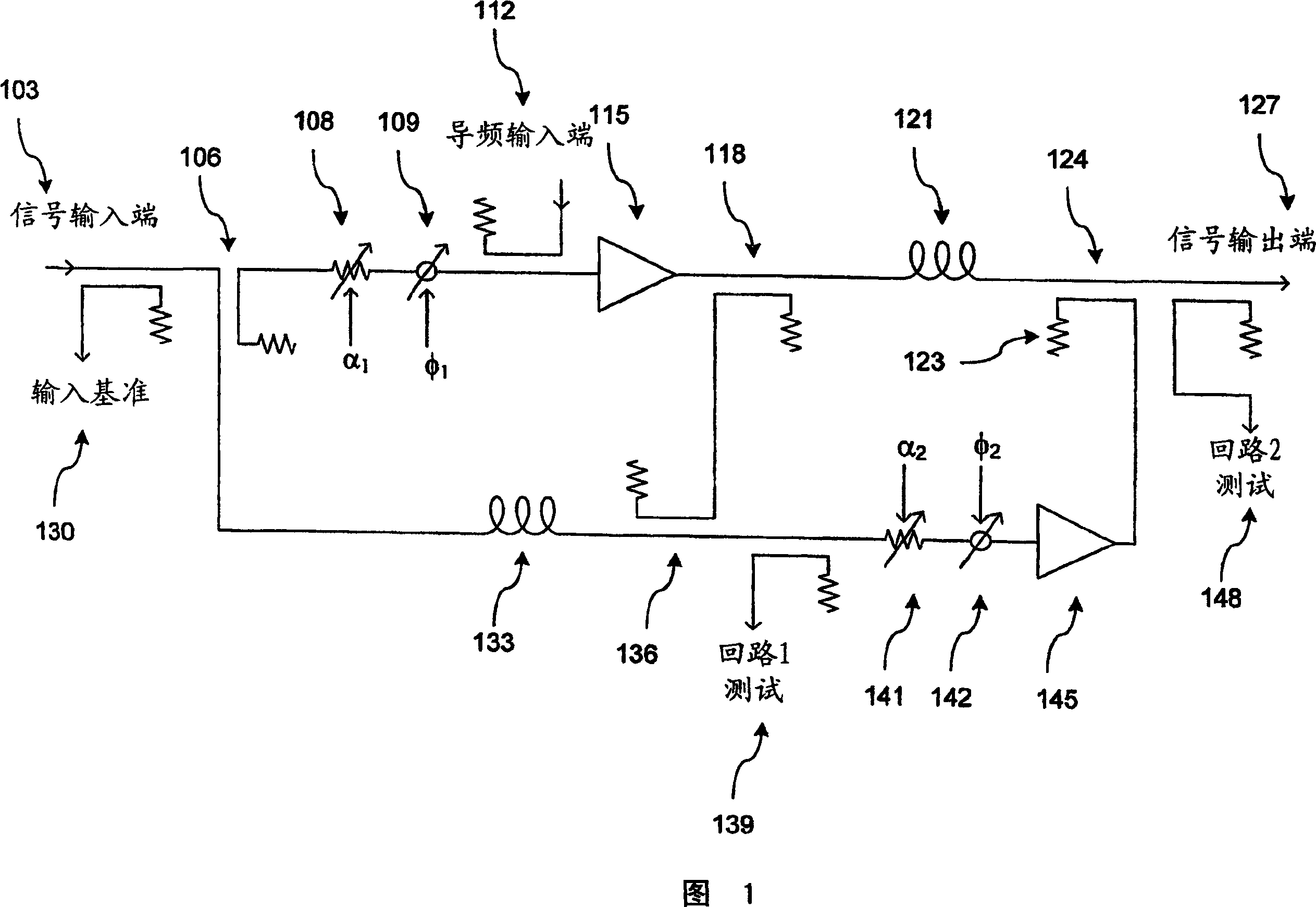
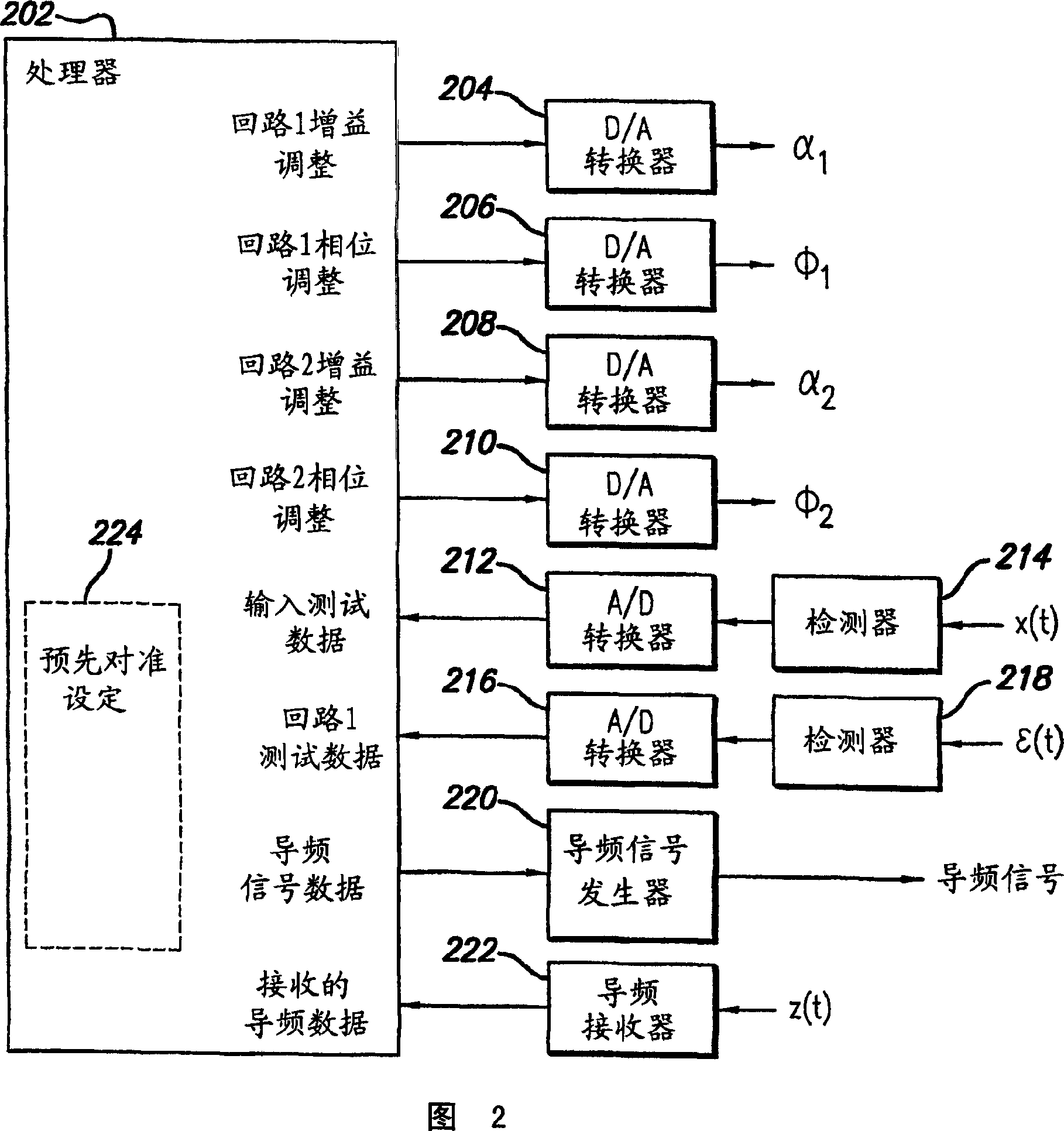
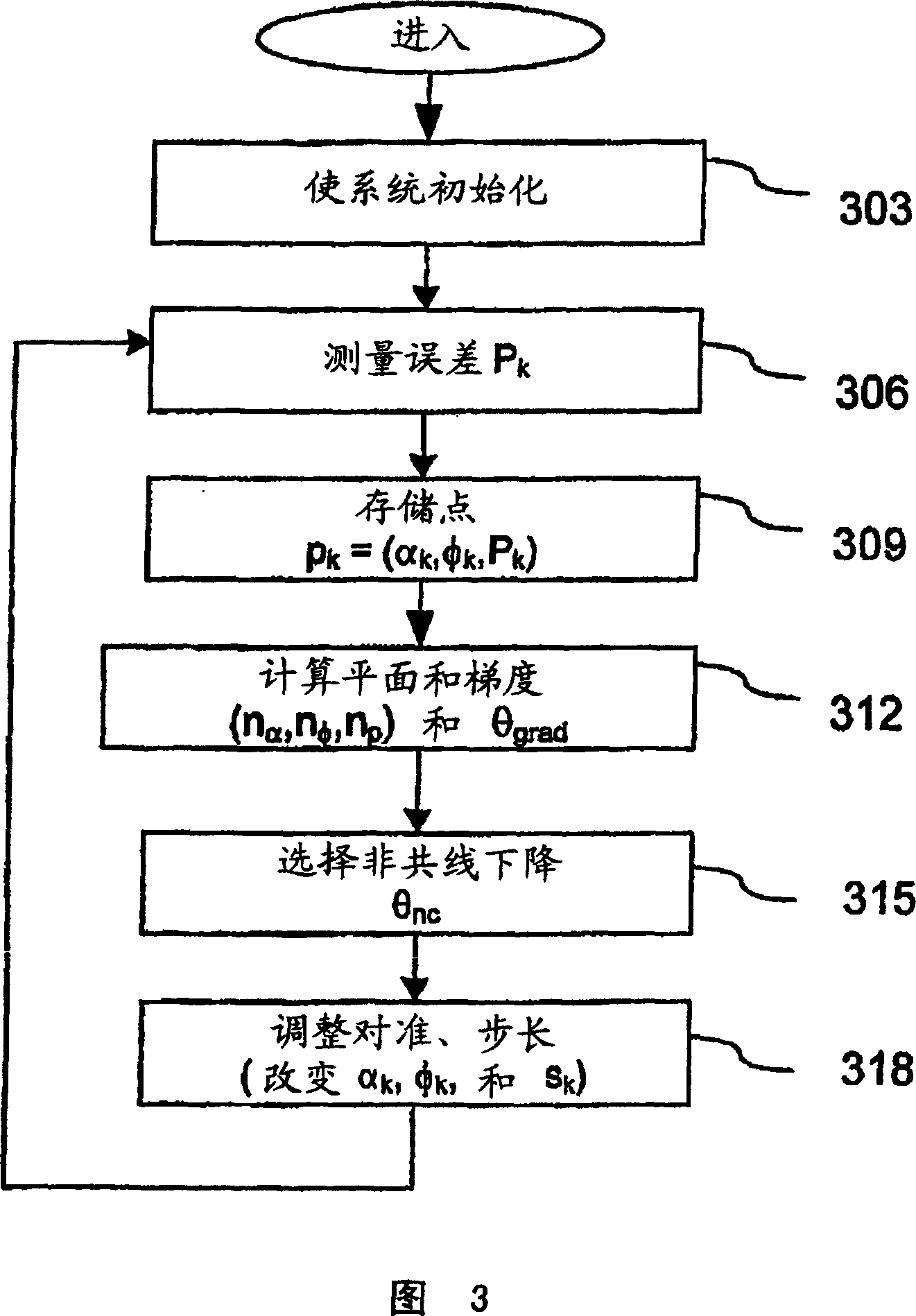
A fast search algorithm for loop alignment of a feed forward amplifier is disclosed. The algorithm controls a processor (202) that adjusts, digitally, the gain and phase of the loop alignment based on power measurements at the input and output of cancellation combiners, to find the optimal setting. A ''non-collinear descent'' algorithm is used to search, iteratively, for the minimum within an error surface. For loop alignment, the error surface is defined by the set of measurement points comprising the alignment settings and the associated cancellation residuals. For the case of first loop alignment, the cancellation residual is measured using the ratio of two power detectors (214, 218) located at the input and after the cancellation (error) combiner. For second loop alignment, cancellation is estimated using the residual pilot power detected at the output of the amplifier. The preferred alignment method uses three successive measurements to estimate the gradient direction with respect to gain and phase shifter settings. The actual descent direction is selected to be close to the gradient direction without being collinear with the most recent alignment adjustments. Quantization of the descent direction simplifies the implementation as well as the enforcement of the non-collinearity constraint on successive alignment settings. Two different step size selection approaches are disclosed, however, any standard step size selection approach may be employed.

Description

[0001] Related application information [0002] This application claims priority to Provisional Application No. 60 / 552,405, filed March 11, 2004, which is incorporated by reference in its entirety. technical field [0003] The present invention relates to power amplifiers. In particular, it relates to an adaptive feedforward power amplifier and a method for controlling a feedforward amplifier. Background technique [0004] An RF amplifier is a device used to replicate the RF signal present at the input, thereby producing an output signal with a much higher power level. The increase in power from the input to the output is called the "gain" of the amplifier. When the gain remains constant over the dynamic range of the input signal, the amplifier is said to be "linear". Amplifiers are limited in their ability to deliver power because gain and phase variations, especially saturation at high powers, make all practical amplifiers non-linear as the input power level varies. Th...

Claims


Application Information

Patent Timeline
IPC IPC(8): H03F1/00
Inventor R·N·布赖思怀特
Owner INTEL CORP
Why Eureka
Try Eureka