Catalysts useful for biomass pyrolysis and bio-oil upgrading

a biomass pyrolysis and bio-oil technology, applied in the field of catalysts, can solve the problems of non-uniform heating and limited heat transfer in previous approaches, and achieve the effect of improving fuel quality

Active Publication Date: 2018-07-03
BOARD OF SUPERVISORS OF LOUISIANA STATE UNIV & AGRI & MECHANICAL COLLEGE
View PDF5 Cites 0 Cited by
  • Summary
  • Abstract
  • Description
  • Claims
  • Application Information

AI Technical Summary

Benefits of technology

[0044]We have discovered improved catalysts that are useful in transforming biomass to bio-oil, improved methods for making such catalysts, and improved methods of transforming biomass to bio-oil using the catalysts. The catalysts are especially useful for, but are not limited to, microwave- and induction-heating based pyrolysis of biomass, solid waste, and other carbon-containing materials into bio-oil. The catalysts can also be used for upgrading the bio-oil to enhance its fuel quality.
[0046]In a preferred embodiment, pyrolysis is carried out as a continuous process (although batch mode may also be used). The biomass may be mixed with catalyst particles, or it may pass over a catalyst bed. The catalyst is heated by microwave or induction heating, and the catalyst rapidly heats the biomass to a temperature from about 250° C. to about 1000° C., preferably from about 500° C. to about 700° C., in anoxic conditions. The biomass volatilizes into vapors. These vapors can be reheated conductively by the catalyst itself (rather than the other way around, as happens in many prior catalytic methods). The vapors are then condensed into a liquid bio-oil. The preferred system uses an “inverse” thermal flux; i.e., heat is generated directly at the catalyst surface or the surface of the substrate supporting the catalyst, which promotes uniform temperature of the catalyst and helps to reduce catalyst degradation and fouling. Microwave or induction heating increases the mass transfer rate at the catalyst surface, by creating surface currents and heat transfer gradients that preferentially remove products from the catalytic surface, thus making the surface available for new reactants. Even before any “upgrading” occurs, the bio-oil that is initially produced should be more stable during storage.
[0047]Heat transfer in previous approaches has generally been limited by the rate of transfer from electrically- or gas-heated reactor walls to the biomass. Efficient bio-oil production in such a system requires small particle sizes, on the order of 1-2 mm, for reasonable heat transfer rates. Or when microwave heating has previously been used, uneven heating from the uneven electric field distribution has typically caused non-uniform heating. In a preferred embodiment of the new process, a focusing microwave reactor concentrates the microwave energy in the location(s) of the cavity where unreacted biomass is located. Much larger particle sizes may be used in the new process, up to several cm in diameter (e.g., up to: 5 mm, 1 cm, 2 cm, 3 cm, 4 cm, 5 cm, 8 cm, or 10 cm), as heating occurs throughout the volume of the material with microwave heating, or as heating occurs at multiple heating surfaces with induction heating. The use of supported metal and ceramic catalysts enhances the efficiency of bio-oil production and bio-oil quality. Small scale (e.g., ˜100 μm to ˜5 mm, preferably ˜1 mm) supports in the form of metallic balls, rods, mesh or foam are coated with a layer (e.g., a nanoscale layer) or metal, metal oxide, or ceramic catalyst. In a preferred approach, the catalyst / support combination is formed through a self-assembly, seed / growth mechanism.

Problems solved by technology

Heat transfer in previous approaches has generally been limited by the rate of transfer from electrically- or gas-heated reactor walls to the biomass.
Or when microwave heating has previously been used, uneven heating from the uneven electric field distribution has typically caused non-uniform heating.

Method used


Image

  • Catalysts useful for biomass pyrolysis and bio-oil upgrading
  • Catalysts useful for biomass pyrolysis and bio-oil upgrading
  • Catalysts useful for biomass pyrolysis and bio-oil upgrading

Examples


example 1

Substrate Production

[0075]A Pt-stainless steel substrate was produced by chemically reducing Pt(s) from platinum salt onto the surfaces of stainless steel particles. The deposition process used formaldehyde as the reducing agent, sodium hydroxide as a stabilizing agent, and chloroplatinic acid hexahydrate solution as the platinum source.

[0076]Stainless steel particles (type 316, diameter 4.8 mm) were first washed with deionized water and ethanol, and then dried in an oven at ˜100° C. The surface of the stainless steel was then plasma-oxidized for 30 sec in vacuum, chemically converting the metal surface into its oxide. This primed the surface for coupling with a silane linker, which acted as a coupling agent between organic and inorganic materials. The silane linker was formed by hydrolyzing alkoxy groups in the molecule to form a silanol. The hydroxyl groups were then hydrogen-bonded to the substrate, releasing water molecules.

[0077]The silane linker used in an initial prototype wa...

example 2

Analysis After Induction Heating

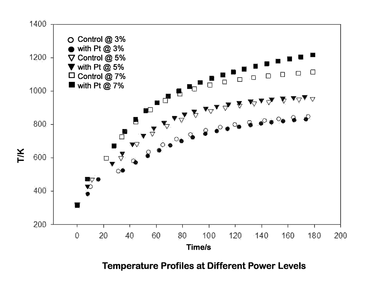
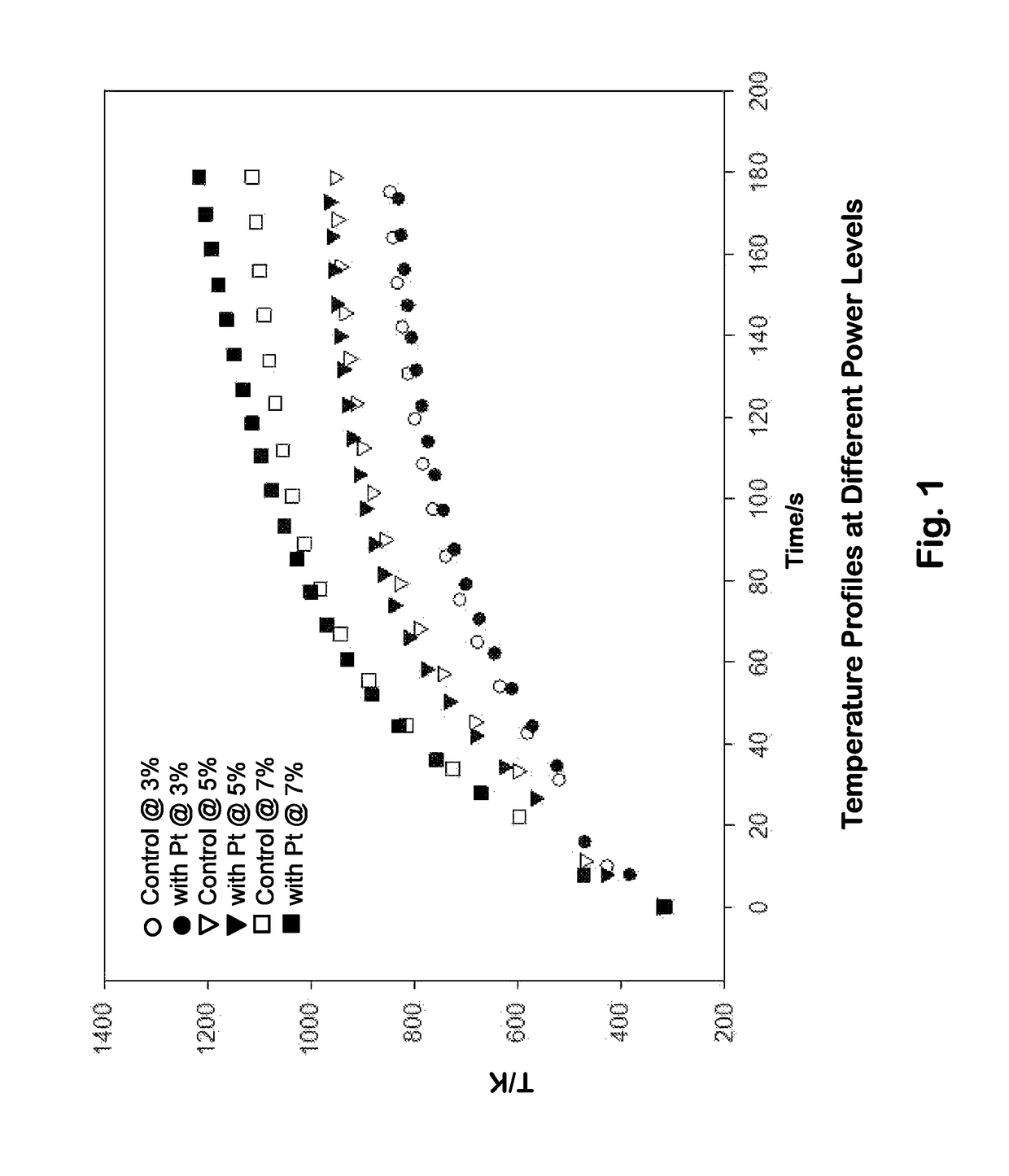
[0083]The platinum-functionalized stainless steel balls were heated with an induction heater at a higher frequency (˜150 to ˜400 kHz) at three different power levels: 150 W (3%), 250 W (5%) and 350 W (7%). Thermal characteristics were compared to those of untreated stainless steel balls. Three stainless steel balls (functionalized or untreated) were placed in a ceramic crucible and heated inside the induction coil during each run.

[0084]Temperature plots compared steel balls with Pt to steel balls without Pt at three power levels: 3%, 5%, and 7% (output=5 kW), as a function of time. As illustrated in FIG. 1, only minor differences in temperature profiles were observed; the platinum deposition did not substantially alter the temperature reached by the stainless steel balls when heated with an induction coil. The temperature profiles were fitted to a simple exponential curve, with three parameters (T0, a, and b):

T(K)=T0+a*(1−bt(s))

[0085]The heating param...

example 3

or Induction Pyrolysis

[0089]One embodiment of the present invention employed the catalyst in an induction heating system (RDO-LF model no. 5-35 / 100-3). A range of temperatures from 400° C. to 800° C. was tested to determine the effect on liquid pyrolysis yield. The induction heater was a low frequency model (RDO Induction LLC, Washington, N.J.) operated in the range 35-100 kHz using a 5 kW power supply. The reaction tube was a 310-stainless steel tri-clamp tube, 419 mm length, 34.4 mm inner diameter, and 38.1 mm outer diameter. An outlet with a 16.5 mm inner diameter was located 29.4 mm from the end of the reaction tube connected to the inlet airflow. The system was purged of oxygen using a continuous flow of argon gas at 1 L / min.

[0090]FIG. 3a schematically depicts a prototype embodiment of the pyrolysis setup. The induction coil was a ten-loop, rubber-coated copper coil with an overall length of 285 mm and an inner diameter of 59 mm. The reaction tube temperature was monitored by a...


PUM

PropertyMeasurementUnit
temperatureaaaaaaaaaa
frequenciesaaaaaaaaaa

Abstract

Catalysts useful in transforming biomass to bio-oil are disclosed, as are methods for making such catalysts, and methods of transforming biomass to bio-oil. The catalysts are especially useful for, but are not limited to, microwave- and induction-heating based pyrolysis of biomass, solid waste, and other carbon containing materials into bio-oil. The catalysts can also be used for upgrading the bio-oil to enhance fuel quality.

Description

[0001]This is the United States national stage of international application PCT / US2014 / 043827, international filing date Jun. 24, 2014, which claims the benefit of the Jun. 24, 2013 filing date of U.S. provisional patent application Ser. No. 61 / 838,565; and of the Jun. 25, 2013 filing date of U.S. provisional application Ser. No. 61 / 839,081; and of the Jun. 17, 2014 filing date of U.S. provisional application Ser. No. 62 / 013,020 under 35 U.S.C. § 119(e). The complete disclosures of all three priority applications are hereby incorporated by reference in their entirety.[0002]The development of this invention was partially funded by the United States Government under grant number CBET-1258821 awarded by the National Science Foundation. The United States Government has certain rights in this invention.TECHNICAL FIELD[0003]This invention pertains to catalysts useful in transforming biomass to bio-oil, methods for making such catalysts, and methods of transforming biomass to bio-oil.BACKG...

Claims


Application Information

Patent Timeline
Patent Type & Authority Patents(United States)
IPC IPC(8): B01J37/02B01J37/12C10B57/06C10B53/02B01J23/42C10K3/02C10G1/08B01J35/00B01J37/16C10B19/00B01J29/40B01J35/02B01J31/00
CPCB01J37/0225B01J35/0033B01J37/0209B01J37/0217B01J37/0219B01J37/0246C10B53/02C10B57/06C10G1/086C10K3/02B01J23/42Y02E50/14B01J29/40B01J31/00B01J35/023B01J37/16C10B19/00B01J23/40B01J23/48B01J23/52B01J23/70B01J29/44B01J37/0221B01J37/0226B01J37/0228B01J37/06B01J37/12B01J37/349B01J2229/32C10G1/06C10G3/44C10G3/47C10G15/08C10G2300/1011C10G2400/04Y02E50/10Y02P30/20
Inventor BOLDOR, DORINHAYES, DANIEL
Owner BOARD OF SUPERVISORS OF LOUISIANA STATE UNIV & AGRI & MECHANICAL COLLEGE
Why Eureka
Try Eureka